


Truck Scales – Integration
Last Updated On January 21, 2026 • 10 min read
Introduction: From Planning to Operation
A truck scale project moves through several coordinated stages, beginning with site assessment and ending with installation and system integration. Each stage affects cost, schedule, and overall project efficiency. Most challenges arise from overlooked civil details such as space constraints, drainage, or soil conditions, which can create unplanned construction work or additional expenses later.
The process typically follows these steps:
- Site review and permitting to confirm available space, truck flow, and access routes.
- Scale selection and purchasing based on required capacity, layout, and budget.
- Foundation and civil works including excavation, forming, and curing.
- Scale installation and wiring once the foundation is ready and level.
- Calibration and inspection to confirm legal and operational readiness.
- Integration and commissioning for indicators, kiosks, and automation systems.
Good planning allows these stages to proceed smoothly and within budget. Understanding how they connect helps project managers avoid delays and unexpected costs, particularly when more advanced automation or data systems are part of the project scope.
1. Site Planning and Design
Proper site planning determines how well a truck scale fits within a facility’s workflow and how costly the installation will be. The process begins with identifying a location that provides safe truck access, stable ground conditions, and clear space for installation and maintenance. Early consideration of these factors prevents costly civil modifications once construction starts.
Key points to evaluate include:
- Traffic Flow: Ensure vehicles can approach, weigh, and exit safely without reversing or tight turns. Consider both loaded and empty truck movements.
- Space and Accessibility: Allow adequate clearance for installation equipment, calibration trucks, and future maintenance access.
- Soil Conditions: Check bearing capacity and drainage. Poor soils may require piling, concrete pads, or added reinforcement that can affect cost.
- Drainage and Elevation: Avoid low-lying areas where water can collect around the foundation. Proper grading protects both the scale and its electronics.
- Electrical and Communication Access: Confirm available power, conduit paths, and communication lines for indicators or automation equipment.
- Environmental Conditions: Account for frost depth, corrosion risk, and other climate factors that may influence foundation design and material selection.
A well-planned site layout helps control project budgets and shortens installation time. Coordinating these details with the scale supplier and civil contractor early in the process ensures the foundation, cabling, and operational requirements are aligned before construction begins.
2. Engineering and Documentation
Once the site layout is confirmed, the next step is preparing the technical documentation needed for design approval, construction, and installation. Clear and complete drawings prevent confusion between contractors, reduce rework, and help maintain control over project costs.
Typical documentation includes:
- Foundation Drawings: Specify footing dimensions, rebar placement, concrete strength, and drainage details. Proper foundations prevent uneven settling and reduce long-term maintenance.
- Scale Assembly Drawings: Show how deck modules, load cells, junction boxes, and cabling are arranged. These drawings guide the installation sequence and ensure compatibility between mechanical and electrical components.
- Electrical and Communication Plans: Identify conduit routes, junction box locations, and connections to indicators or kiosks. Planning these routes in advance avoids last-minute trenching or modifications.
- General Arrangement (GA) or Site Drawings: Combine scale, foundation, and building layouts to confirm clearances for vehicles, service access, and calibration trucks.
- .STEP and CAD Files: Useful for engineers integrating the scale into broader site or facility designs.
Accurate drawings also support permitting and help contractors quote more precisely. Providing all documentation to the construction and installation teams before work begins ensures the project stays within scope and avoids delays due to missing or inconsistent information.

3. Procurement and Bidding
Procurement connects the design phase to construction. Once the layout and documentation are complete, buyers begin evaluating suppliers and requesting quotations. A good procurement process compares both technical merit and long-term value, not just price.
What to Look for in a Proposal
When comparing bids, focus on measurable technical factors rather than brand claims or marketing language.
| Evaluation Area | What to Verify | Why It Matters |
|---|---|---|
| Structural Design | Type of deck (U-Channel or I-Beam), deck thickness, module connections | Determines load distribution, rigidity, and lifespan |
| Fabrication Standards | Welding method, material grade, dimensional tolerances | Ensures consistency and structural strength |
| Coating System | Surface prep (e.g. SA 2.5), number of coats, curing method | Defines corrosion resistance and long-term appearance |
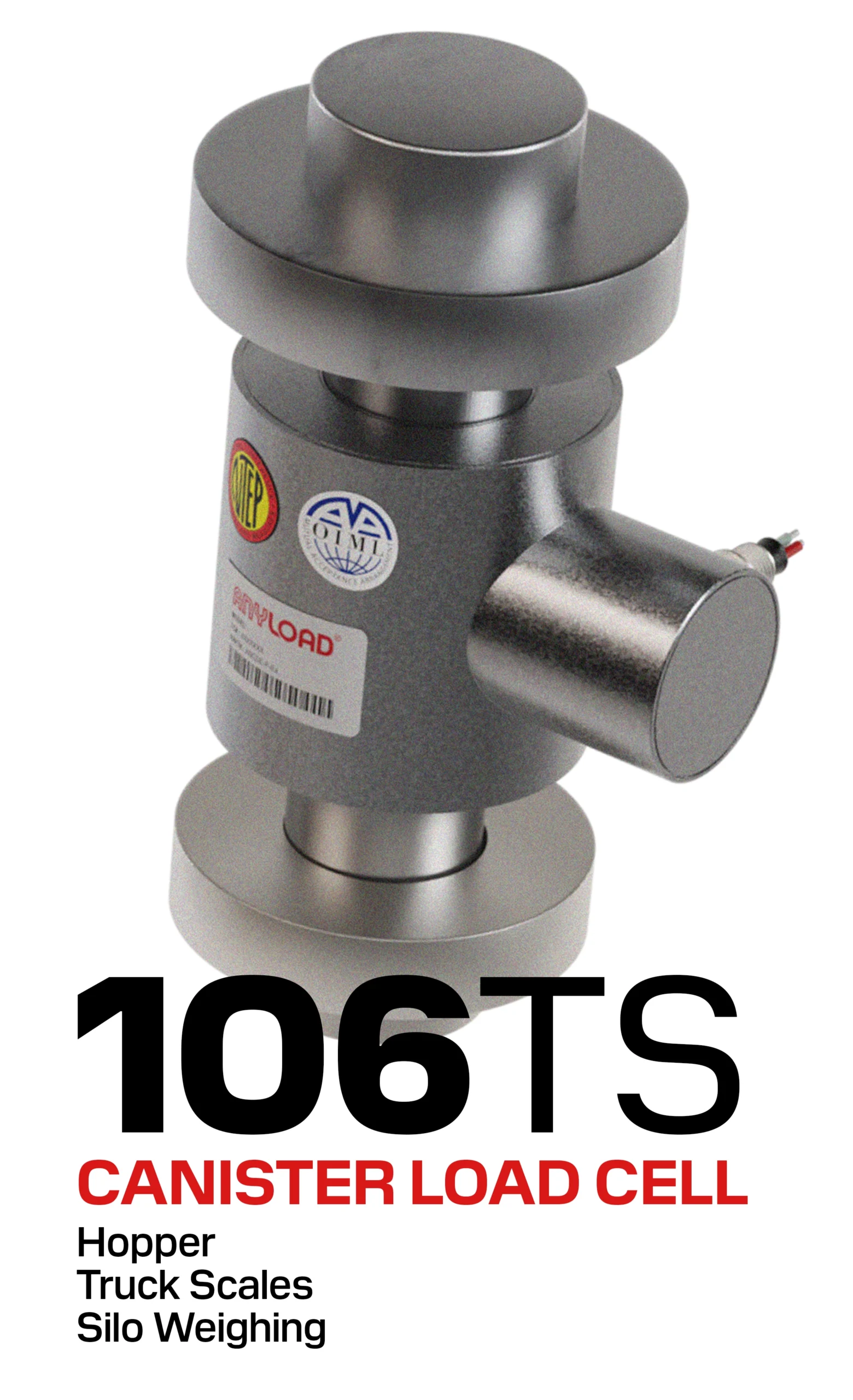
| Load Cell Certification | OIML / NTEP approval, accuracy class, mounting system | Impacts measurement reliability and ease of service |
| Documentation Quality | Foundation and layout drawings, CAD models, specifications | Helps contractors quote accurately and reduces installation errors |
Avoiding Common Procurement Pitfalls
- Overemphasis on Branding: Large multinationals often market proprietary systems that add cost without measurable performance benefits.
Incomplete - Documentation: Missing or vague drawings can lead to hidden civil costs once construction begins.
- Lowest-Bid Bias: The cheapest option may omit design, fabrication, and coating steps or may have limited aftersales support that shorten lifespan and raise maintenance costs later.
- Gold-Plating: Over-specified systems with unnecessary accessories or automation can inflate budgets without meaningfully improving functionality.
ANYLOAD’s Approach
ANYLOAD supports the procurement and bidding process by providing:
- Comprehensive drawings, specifications, and certification details
- Transparent descriptions of fabrication and coating processes
- Clear scope definition to help buers compare proposals on technical merit
- Practical options for modularity, protability, and integration suited to real-world applications
This approach enables buyers to balance performance, reliability, and cost. Experienced purchaser recognize that value lies in solid engineering and documented quality, not in the highest price or most elaborate marketing language.
4. Truck Scale Foundations & Civil Works
A truck scale’s performance depends heavily on the foundation beneath it. The weighbridge design determines how forces are distributed, but the foundation ensures that those forces remain stable and consistent over time. A solid, well-constructed foundation maintains calibration, prevents uneven loading, and protects both the structure and load cells from premature wear.
Why Foundations Matter
Truck scales endure repetitive, high-impact loads from braking, accelerating, and turning vehicles. Seasonal ground movement, frost, and drainage all influence foundation behaviour. A poor or uneven foundation leads to:
- Calibration drift
- Uneven load distribution
- Premature wear on load cells and mounts
- Voided legal-for-trade certification
For both permanent and portable scales, foundation design must balance load-bearing strength, site conditions, cost, and maintenance access.
Engineering Drawings and Local Certification
Most regions require that foundation drawings be reviewed or stamped by a licensed civil or structural engineer before construction. ANYLOAD provides detailed general foundation drawings that define pier locations, bearing dimensions, drainage paths, and conduit placements. These documents serve as the engineering basis for local adaptation. Typically, the process works as follows:
- ANYLOAD supplies foundation drawings with each truck scale quotation or order.
- A local civil or structural engineer reviews the drawings, verifies soil and climate conditions, and reissues stamped drawings compliant with local codes or permitting requirements.
- The foundation contractor builds from these stamped drawings, with the scale dealer verifying dimensions prior to installation.
In some jurisdictions, especially for private or agricultural installations, stamped drawings may not be required. However, using professional engineering review ensures that the design suits local soil and environmental conditions and prevents costly modifications later.
Key Foundation Design Considerations
- Soil Bearing Capacity: Verify compaction and stability before construction.
- Drainage: Maintain slope and discharge away from the scale to prevent corrosion.
- Frost Protection: Extend foundation depth below frost line in cold regions.
- Access and Service Space: Allow room for calibration trucks, inspection, and cleaning.
- Electrical Grounding: Provide grounding points for lightning and surge protection.
A properly built foundation sets the stage for long-term scale performance. Cutting corners on this step can result in repeated adjustments, downtime, and unexpected costs during installation or future maintenance.

5. Common Foundation Types
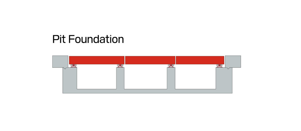
1. Pit Foundation
- Scale is installed flush with ground level.
- Ideal for sites with limited space or need for minimal approach ramps.
- Better protection from lateral movement due to embedded structure.
- Requires drainage system to manage water ingress.
- Typically more expensive and involved in site prep.
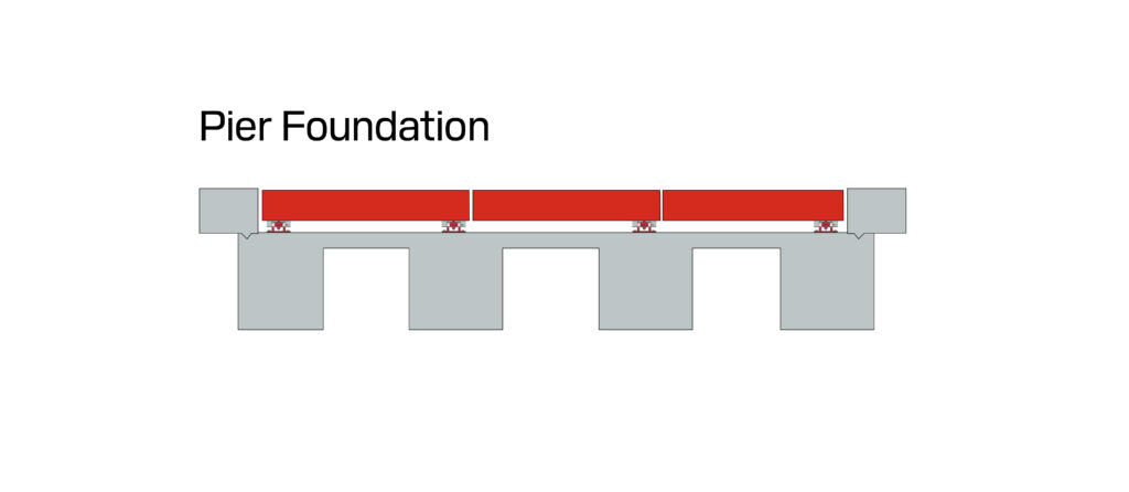
2. Pier Foundation
- Discrete reinforced concrete piers placed under load points.
- Cost-effective for stable soil or cold climates (resists frost heave).
- Requires precise levelling and may settle unevenly over time.
- Popular in northern or rural installations.
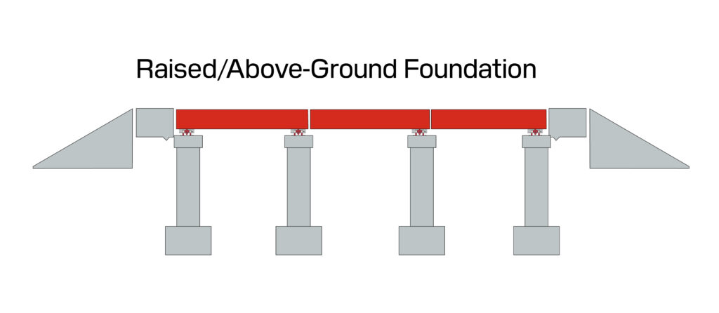
3. Raised / Above-Ground Foundation
- Scale deck sits above grade with ramps.
Simplifies cleaning, drainage, and access for maintenance.
Adds overall height
Ramps must meet regulatory specifications.
More prone to debris or snow accumulation under deck.
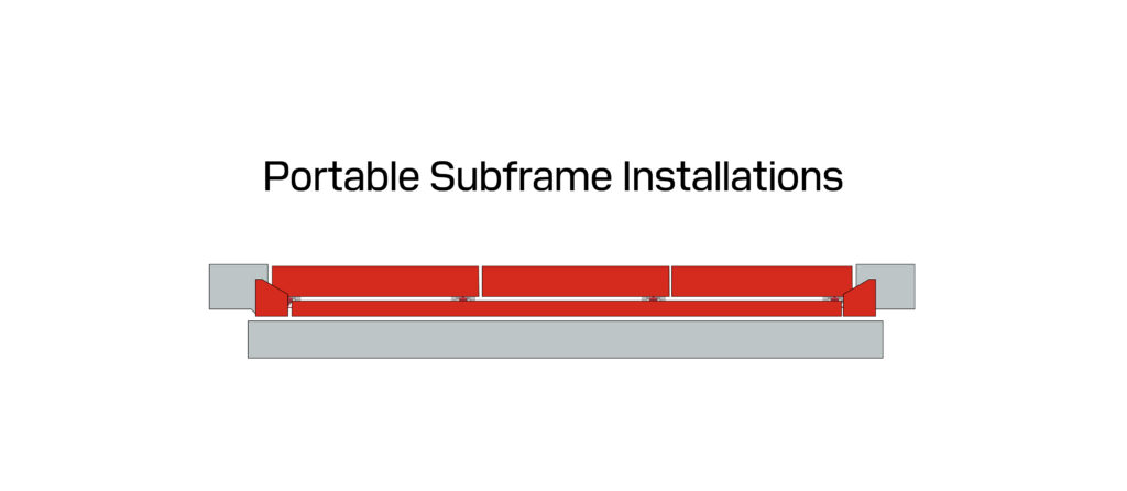
4. Portable Subframe Installations
- Steel subframe allows the scale to be deployed on compact gravel or prepared pads without pouring permanent concrete.
- Ideal for seasonal use, agricultural operations, or temporary jobsites.
- Still requires a level, rigid surface with adequate drainage to maintain accuracy and prevent shifting.
Concrete Foundation Contractor Selection
The quality of the concrete work has a direct effect on installation success. In many cases, installation delays are caused by foundations that do not meet specified dimensions or elevations. Even small deviations in pier spacing, pit width, or embedded conduit placement can prevent the deck from fitting correctly.
When selecting a foundation contractor:
- Work with an experienced vendor. Choose a contractor familiar with weighbridge or industrial foundations that tend to require tighter tolerances, not just general paving or building work.
- Use the scale dealer’s recommended vendor when possible. The scale dealer often have experience with local contractors who understand the tolerances required. Even if their quote is higher, the weighbridge installer would be responsible for making the system fit, saving you time and risk later.
- Require drawings and supervision. Use the scale supplier’s foundation drawings and verify key dimensions before and after pouring concrete. The contractor should confirm placement of anchor bolts, conduit paths, and drainage lines before concrete work begins.
- Avoid cost cutting at this stage. Errors in concrete work are expensive to correct and can delay the project substantially. Proper site prep and curing ensure long-term performance and easier installation.
6. Installation and Commissioning
Truck scale installation is carried out by qualified scale dealers or service providers who specialize in mechanical assembly, wiring, and calibration. Their work ensures that the scale is levelled, aligned, and certified for operation. While end users do not normally perform these tasks, understanding the process helps in planning site access, scheduling, and minimizing disruption to normal operations.
If you are preparing for an installation and do not already have a contractor or service provider, contact ANYLOAD for a referral to an authorized local dealer. Our partners are experienced in handling both new installations and replacements on active sites.
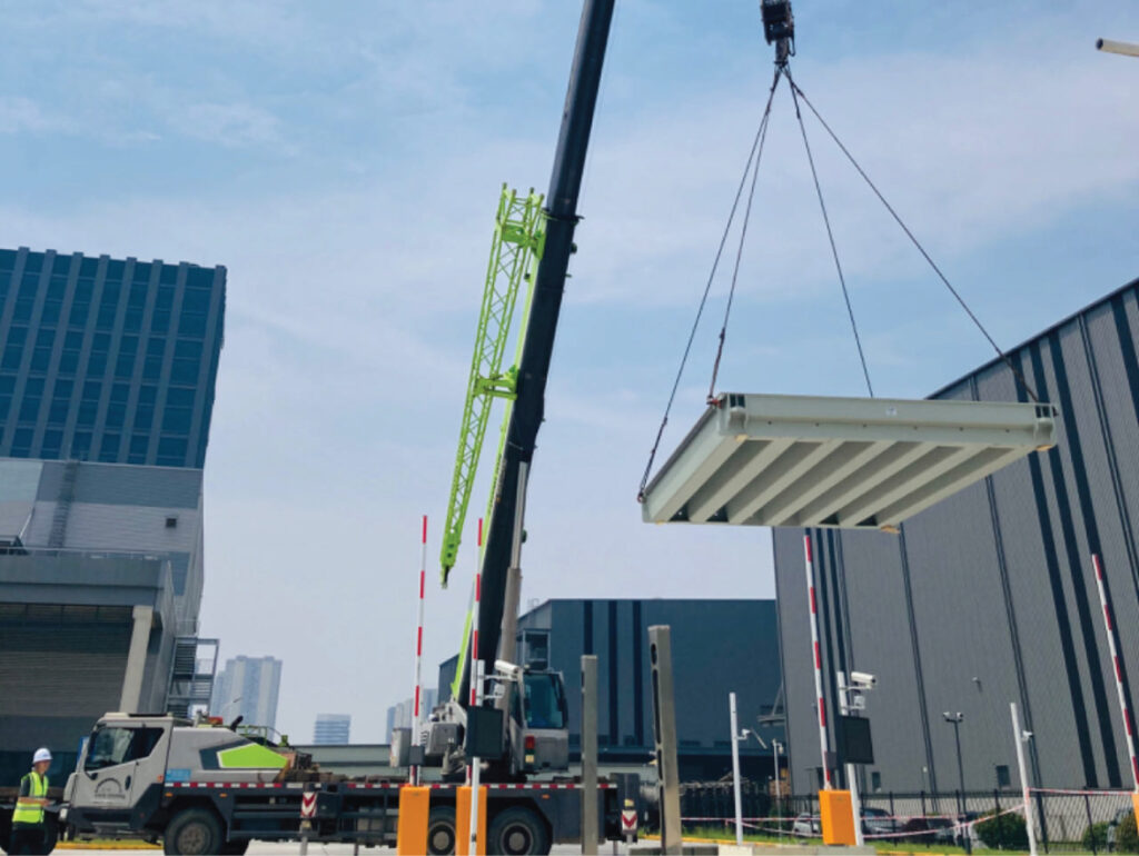
Installation
Preparing for Installation
- Ensure clear access for cranes, calibration trucks, and service vehicles.
- Confirm that the foundation has cured, is clean, and is ready for placement.
- Verify that electrical supply, conduit, and drainage paths are available and match the foundation drawings.
- Allocate temporary work space for technicians to assemble modules, route cabling, and perform calibration.
Work Performed by the Dealer
Most of the installation process is completed by the dealer or their certified service team, including:
- Weighbridge Assembly: Placing and aligning deck modules on the foundation or subframe and securing connections.
- Load Cell and Mount Setup: Installing and levelling load cells and ensuring vertical alignment for load distribution.
- Cabling and Junction Box Wiring: Routing load cell cables through conduit, wiring to junction boxes, and performing signal trimming.
- Indicator and Terminal Installation: Mounting the indicator, connecting communication lines, and setting up peripheral equipment such as printers, kiosks, or displays.
- Calibration and Verification: Using certified test weights to adjust and verify accuracy for legal-for-trade use.
- The system is “zeroed out” when the scale is empty to eliminate static bias.
- This baseline becomes the foundation for accurate weighing.
2. Span Calibration
- Certified test weights are placed incrementally on the scale.
- The indicator is adjusted to match known values at various load points.
- Span calibration verifies the system’s linearity and repeatability.
3. Section Testing (for multi-module scales)
- Each scale section is loaded individually to verify uniform performance across the weighbridge.
- Load cell signals are fine-tuned using the junction box.
Legal-for-Trade Verification
Scales used in commercial transactions must be certified by local authorities (e.g. Weights and Measures Inspectors in the U.S. or Measurement Canada). This often includes:
As-found accuracy check
Calibration with certified weights
Documentation of tolerances and serial numbers
Certification sticker applied upon approval
Recalibration
Regulations typically require periodic recalibration depending on usage, jurisdiction, and application type. Additionally, recalibration may be needed after:
- Load cell replacement
- Foundation settling
- Structural damage
- Major environmental changes or relocation of the scale
7. System Integration
While the weighbridge and load cells are at the core of any truck scale, most installations require additional components to turn raw weight readings into actionable data and efficient workflows. These peripheral systems complete the solution from a basic legal-for-trade operation up to a fully integrated logistics hub.
Indicators and Terminals
Every truck scale requires a weight indicator, often mounted in a scale house or kiosk. This device displays live readings and typically handles tare, gross, and net weight calculations. More models support:
- Memory storage for recurring trucks
- Batch or multi-axle weighing modes
- Ticket printing and transaction logging
- Data export via USB, Ethernet, or serial ports