


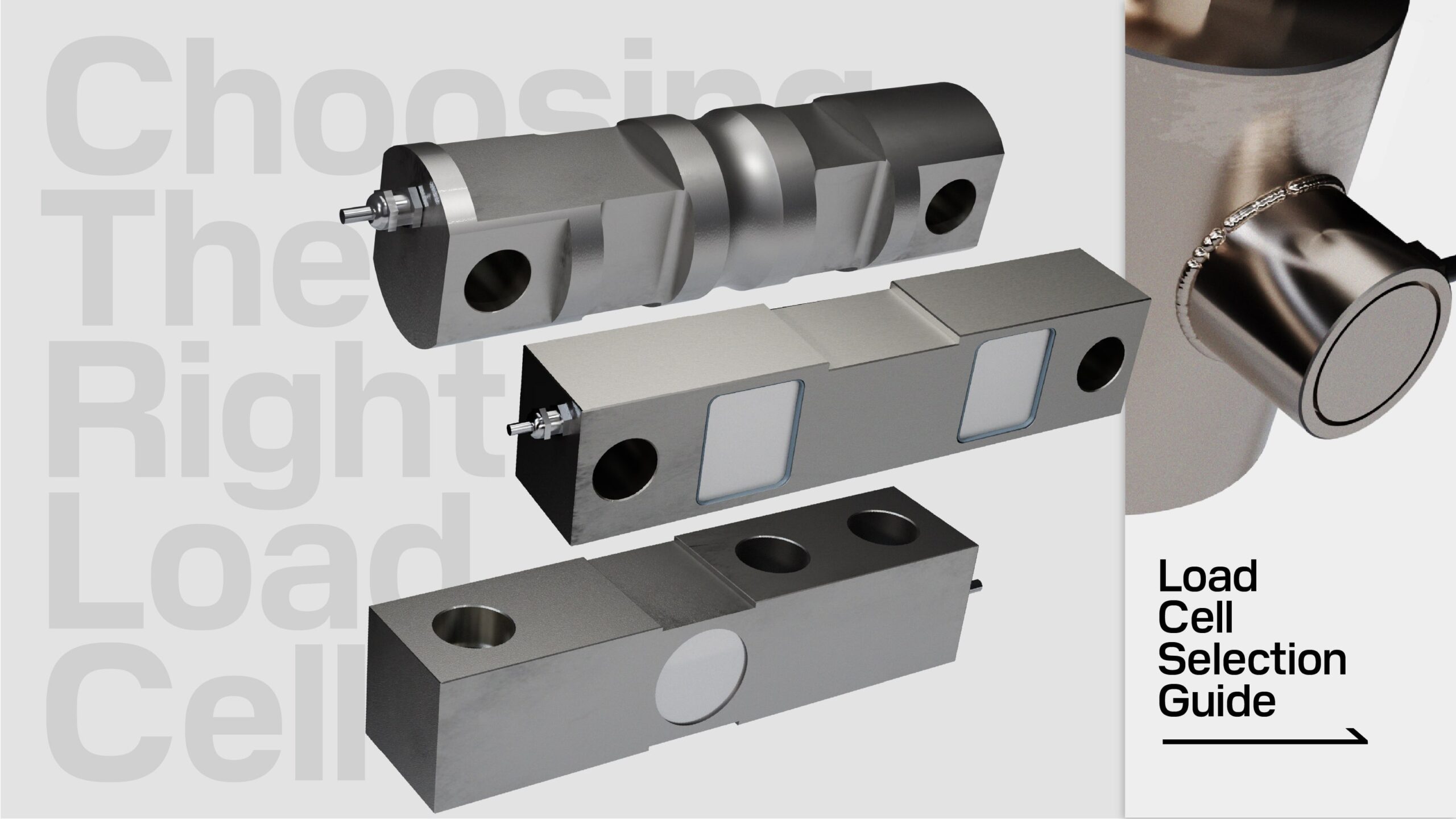
How Does a Load Cell Work?
Last Updated On • 8 min read
1. How Does a Strain Gauge Load Cell Work?
A strain gauge load cell converts force into an electrical signal by means of precision strain gauges, which alter their resistance in response to applied pressure or load.
This conversion is made possible through two primary components of a strain gauge load cell: the strain gauge and the sensing element.
- Strain gauges: A type of variable resistor that changes in resistance output in proportion to the deformation of the metal.
- Element: A machined piece of metal that responds predictably in proportion to an applied force.
The strain gauges are meticulously bonded onto the sensing element, and together, they form the heart of the strain gauge load cell.
To amplify their sensitivity and accuracy, strain gauges are integrated into a Wheatstone Bridge circuit. This circuit enhances the load cell’s ability to detect minute changes in resistance, thereby allowing for exceptionally precise measurements.
Complemented by additional electrical components, the strain gauge load cell is a system fine-tuned to deliver precise and reliable signals, essential for a wide array of weighing and force measurement applications.
2. Strain Gauges
What are Strain Gauges?
Strain gauges are precise sensors used to measure mechanical deformation – specifically, the strain of an object. When external forces are applied to an object, stress and strain are the result. Strain is the ratio of the deformation to the original length, and measuring this strain can tell us a lot about the performance and structural integrity of the material or object being tested. When a strain gauge is bonded to a strationary object, it can thus measure the stress or strain it experiences and convert that into an electrical output in the form of changes to resistance.
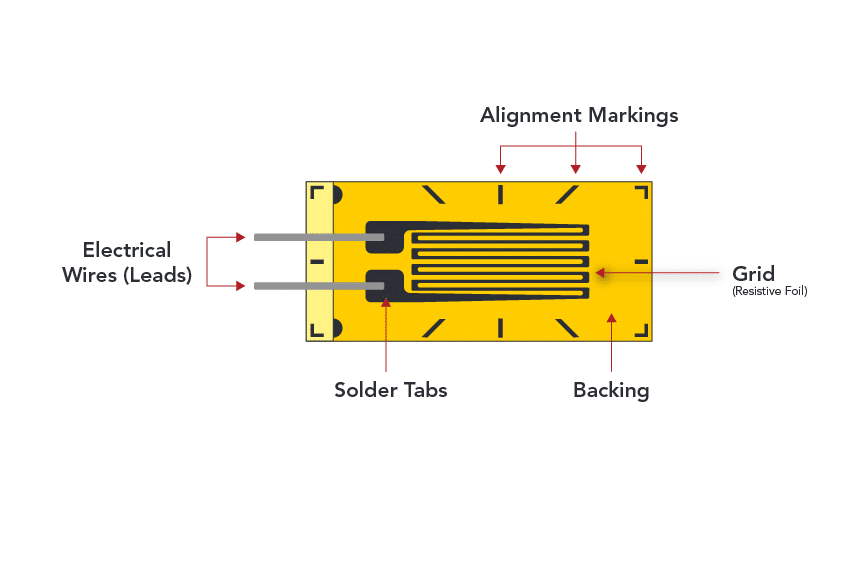
Physically, a strain gauge consists of a thin, metallic foil pattern – the “gauge” – placed onto a flexible backing material, known as the carrier. The foil is usually arranged in a zig-zag pattern to maximize its length within a small area, which increases its sensitivity to strain. When bonded to the surface of the material under test, the gauge deforms along with the material.
How are Strain Gauges Applied in Load Cells?
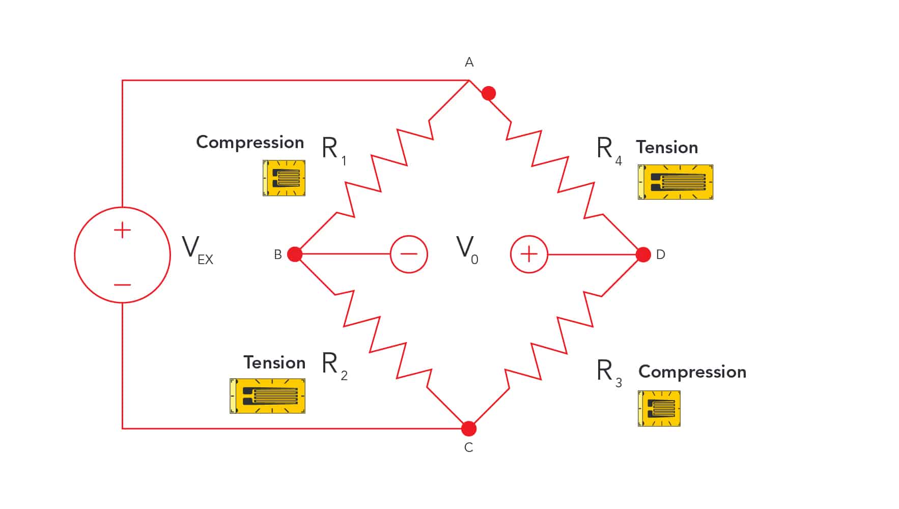
To enhance precision and reduce error, strain gauges are typically integrated into a Wheatstone bridge circuit when used in load cells. The Wheatstone bridge is an electrical circuit used to measure electrical resistance changes with high accuracy. In its most common configuration, it comprises four resistive arms, with strain gauges forming one or more of these arms. When strain alters the resistance of the gauges, it unbalances the bridge, creating a differential voltage that can be measured.
This setup offers several advantages over using a single gauge. It compensates for temperature variations, which can affect resistance readings, and it allows for the measurement of very small changes in resistance due to strain, thus providing greater sensitivity and accuracy. The bridge circuit can be excited with a stable voltage or current, and the resulting output signal, which is a function of the strain, is both stable and repeatable.
3. Sensing Elements
What is a Load Cell Element?
A sensing element (also referred to as a “spring element” or “spring body”) is a precisely machined piece of metal, typically high grade alloy steel, stainless steel, or aluminum. Only a few alloys can be used as there are stringent requirements for strength, linear elasticity, and corrosion resistance. Precision machining along with surface and heat treatment is necessary to further improve performance and durability.
Elements are designed so that when force is applied in a specific direction, it will deform in a predictable and consistent manner. This deformation is not random but occurs in well-defined areas designed to maximize sensitivity and accuracy. The strain gauges, adhered to these areas, experience a change in their physical shape, which in turn alters their electrical resistance. This change in resistance is directly proportional to the amount of deformation, and thus, to the force applied.
The sensing element serves to:
- House and protect the strain gauge and other sensitive electrical components
- Elastically deform in a controlled manner for the strain gauge to measure accurately and repeatably
- Facilitate the integration of a weight or force sensor into various applications requiring specific shapes and sizes
Sensing elements come in a variety of shapes and sizes which are designed and optimized for the type of force it will measure, specific applications, and rated capacities. Some are designed for higher safety factors or durability while others are optimized for sensitivity or response times.
Elements shapes are generally categorized into a few common load cell types:
4. How it All Works Together
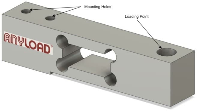
To show how a load cell actually works with all its components together, we will demonstrate using a basic single point load cell. A platform may use an individual single point load cell to measure the compression force.
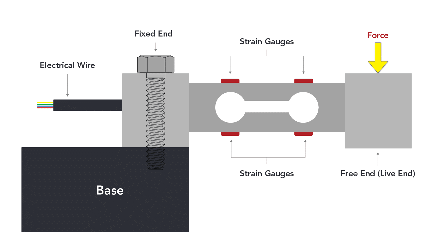
The sensing element of a single point load cell will look similar to this illustration (figure 4.1):
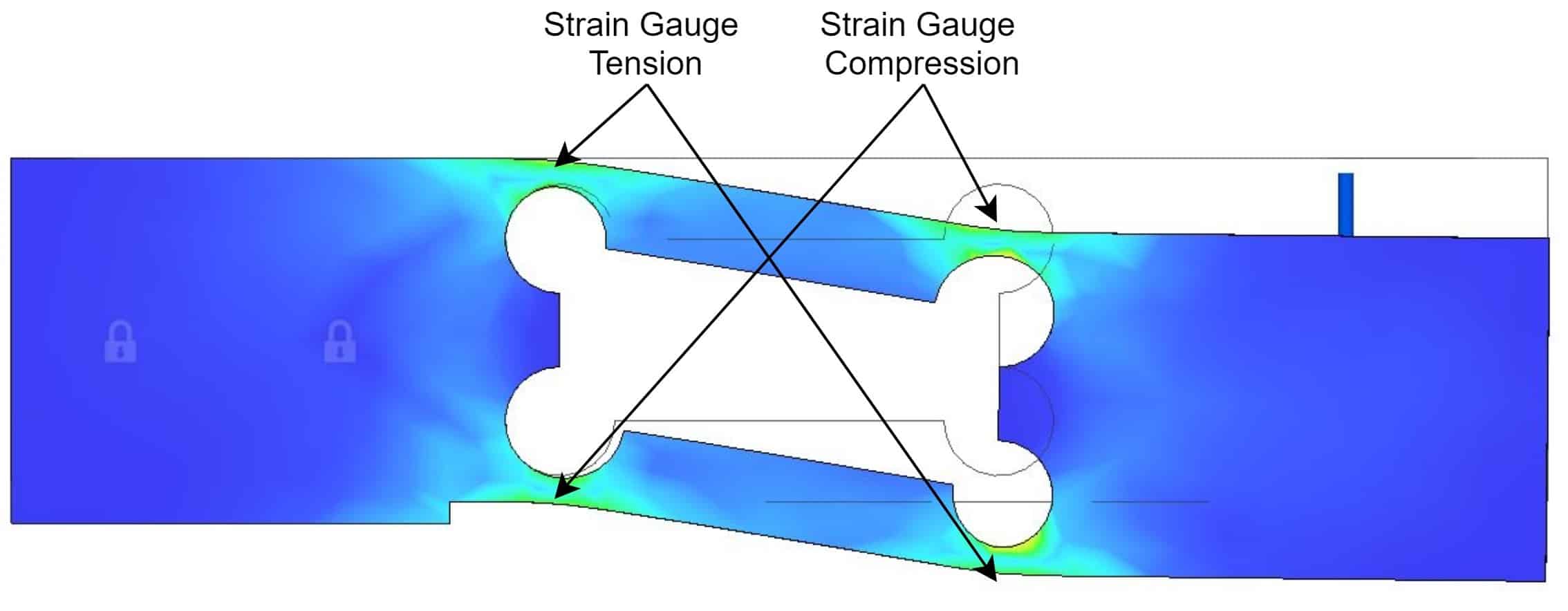
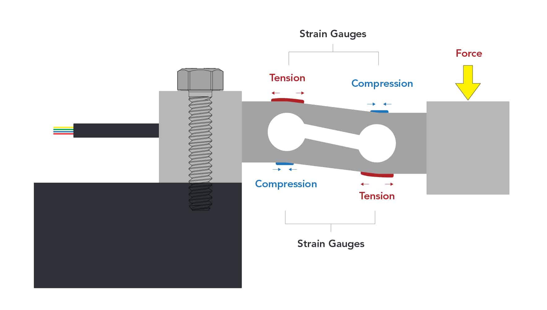
When a load is exerted on the load cell at the loading point, the sensor element will produce strain resembling the following simulation. Strain gauges are generally bonded to the sensor element where the most strain will occur.
The change in the shape of the sensing element is exaggerated for illustration purposes. The typical deflection of most load cells is about 0.1mm to 1mm of at full scale.
The installation process of a load cell depends on its design and is adapted to its specific use case. For example, single ended and single point type load cells are anchored at one end (the ‘fixed end’), securely fastened to a robust structure, while the opposite end (the ‘live end’) remains unattached, free to accurately register the applied load. Correct installation is critical; even slight misalignments or constraints can skew measurements, undermining the load cell’s accuracy.
Calibration is the subsequent crucial phase, fine-tuning the load cell to guarantee a zero balance at rest and precise force measurement during use. This adjustment often entails applying known weights to the load cell and calibrating the output to these standards, ensuring the system’s reliability. Depending on the application’s regulatory environment, certification might also be necessary to meet specific compliance standards.
The final step involves integrating the load cell with a readout or data acquisition system, enabling the transformation of electrical signals into readable weight or force metrics. This connectivity not only facilitates the visualization of measurements but also allows for data interfacing and transmission, a key feature for streamlining operations in various sectors. This cohesive assembly of components and processes ensures that strain gauge load cells deliver dependable and accurate measurements, crucial for the myriad applications they serve.