


Junction Boxes
Last Updated On April 29 • 12 min read
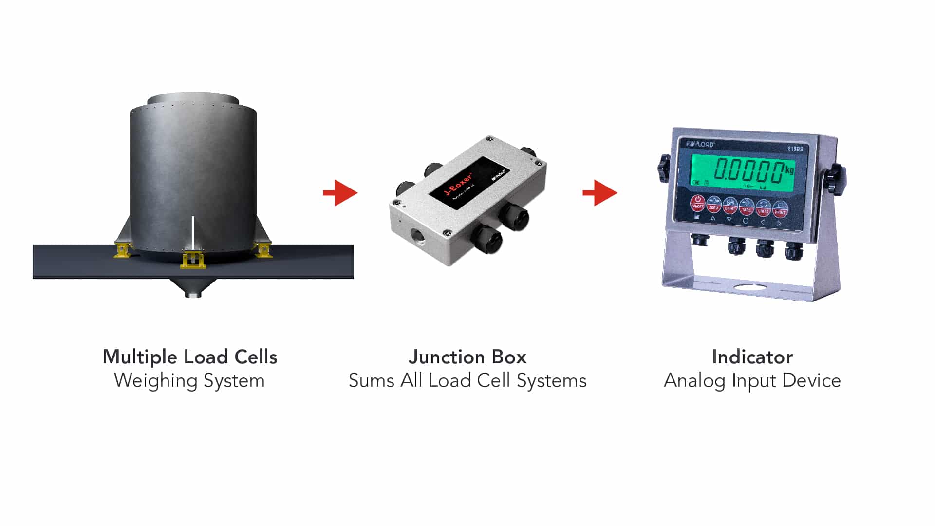
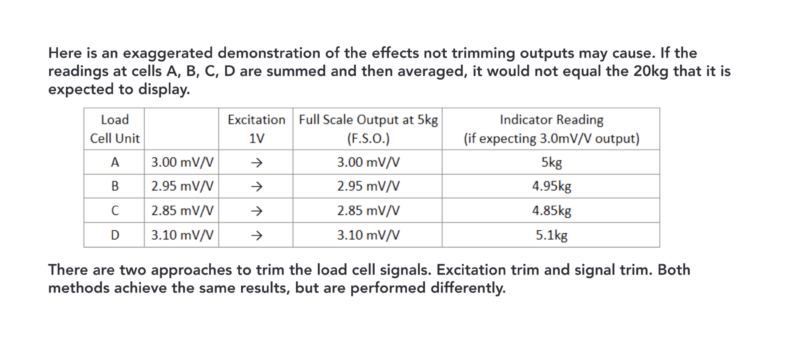
Junction Boxes (also referred to as “summing boxes”) are a critical component in weighing systems involving more than load cell, serving as a central hub where multiple load cell signals are collected, summed, and managed. Whether in large-scale industrial platforms or intricate batching systems, the proper selection, installation, and maintenance of junction boxes are key to achieving optimal weighing results.
1. Introduction to Junction Boxes
Junction boxes distributes power and sums up the signals from multiple load cells and deliver a unified signal to an indicator.
2. Key Functions of a Junction Box
Signal Summation & Distribution:
Signal summation is a key function in junction boxes used with multiple load cell systems, allowing for accurate total weight measurements. In these systems, the load is distributed across various points, each monitored by a separate load cell. The junction box collects the electrical outputs from all load cells, combines them, and sends a single comprehensive signal to the display or control system.
Environmental & Electrical Protection
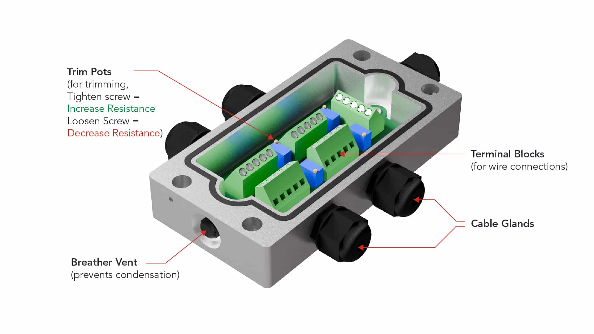
Junction boxes are protect electrical connections against environmental hazards like moisture and dust, as well as electrical disturbances including electromagnetic interference (EMI). Their robust design shields load cell connections from damage and ensures signal integrity by filtering out EMI, crucial in industrial settings. Built-in grounding and surge protection mechanisms safeguard against electric shock and circuit damage from voltage spikes.
Load Cell Trimming
Trimming ensures that the scales with multiple load cells weighs correctly regardless of where the load is applied to the scale by balancing the weight readings from each cell. Junction boxes to ensure that all connected load cells receive or otherwise deliver a consistent voltage. This uniformity is crucial for accurate measurements, as variations in excitation voltage can lead to discrepancies in the load cells’ outputs, leading to inaccurate readings.
3. Types of Junction Boxes
Junction boxes are available in a number of types and configurations depending on the applicational requirements and installation preferences. Each has their specific advantages and trade-offs, which scale technicians evaluate per application. Each type of junction box may be available in excitation trim or signal trim, depending on trimming preference.
Aluminum Junction Boxes
Compact, cost-effective, typically used in smaller 4-channel applications. Vulnerable to salt corrosion.
Stainless Steel Junction Boxes
Wider range of options (4- to 12-channel), corrosion-resistant. Vulnerable to condensation, moisture.
Plastic/Fibreglass Junction Boxes
Tight sealing against moisture. Does not condensate. Plastic may naturally deteriorate over time.
4. How to Connect a Junction Box
Always consult and follow the instructions specific to each junction box. The following are general instructions applicable to most junction boxes on the market, but exceptions may apply.
- Do not cut the cable attached to the load cell
- There should be some amount of slack in the cable, especially where it connects to the load cell so that force is not transferred from the cable into the load cell, which will interfere with your measurements.
- Insert the open end of the load cell cable into the ports
- Install each wire to the terminal block
- Check the datasheet for the color coding
- Make sure each metal wire is in direct contact with the terminal and there are no obstructions by the rubber shielding
- Screw down each wire with a small screwdriver
- Note whether the junction box is signal trim or excitation trim (if trimming)
- Connect the junction box output to the indicator
5. Load Cell Trimming with Junction Boxes
Trimming the outputs of load cells may be required before beginning the calibration of a multi-cell system. This adjustment is done via the junction box to harmonize the weight readings from all cells within the system. By doing so, it helps to ensure that the scale provides consistent measurements, irrespective of where the load is applied to the scale.
- Weight distribution in multiple load cell systems is not equal at each load cell
- Loads are not always applied at the exact same point.
- Vibration, wind, and other agitation can affect weight distribution.
- Weighing structures cannot be fabricated to a tolerance that precisely distribute loads equally across all loading points.
- Natural variation in individual load cell signal output is unavoidable in the load cell manufacturing process.
- Variations often of ±0.01mV or less is very difficult to control.
- These minor variances can accumulate in multi-cell applications.
Junction boxes are have circuit boards configured to trim either the excitation voltage input to the load cell (excitation trim) or the signal output from the load cell (signal trim). Excitation trim junction boxes regulates the excitation voltage delivered to each load cell. Signal trim junction boxes tune the signal output from load cells, adjusting the signal available to the indicator.
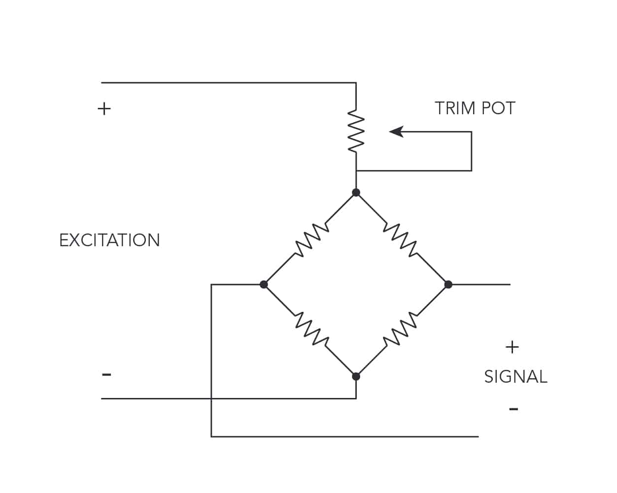
6. Excitation Trim
Excitation trim junction boxes regulates the excitation voltage delivered to each load cell to ensure consistent output from a weighing system. This is done by adding series resistance to the excitation circuit of the load cell, thus reducing the excitation voltage at each cell. The load cell with the lowest mV/V output receives the full excitation voltage while all other load cells receive slightly smaller excitation voltages proportional to the difference in output.
Less Excitation = Less Signal Output
Resistance ➚;Signal➘
Resistance ➘;Signal➚
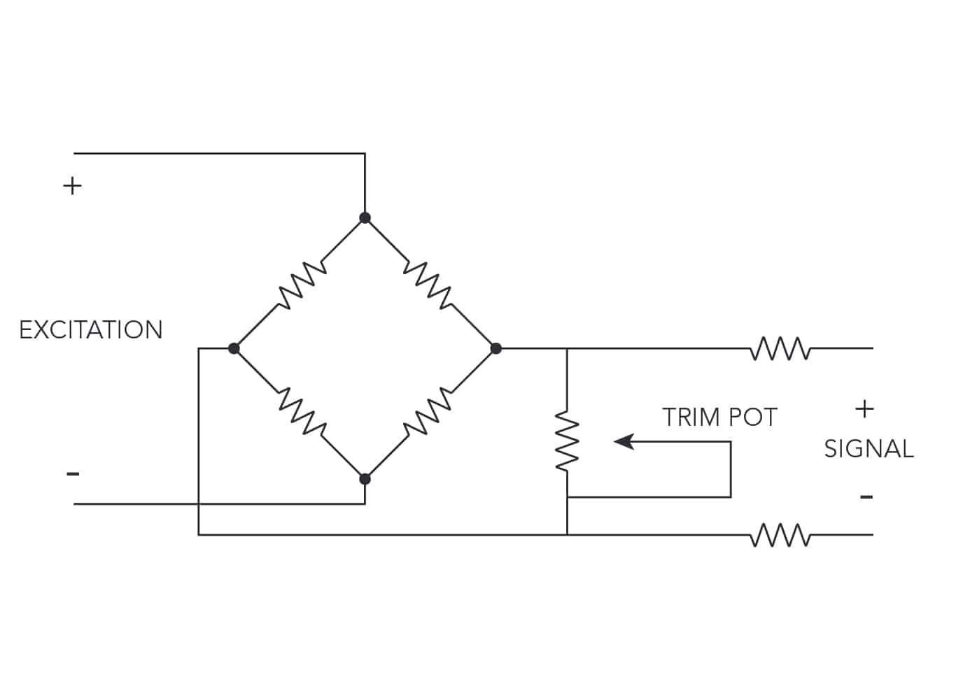
7. Signal Trim
Signal trim junction boxes adds a high parallel resistance between the signal of each load cell, which creates a leakage path that diverts some of the load cell signal away from the indicator. As parallel resistance increases (to the leakage path), more signal is delivered to the indicator.
More load cell signal will be available to the indicator as parallel resistance increases.
Resistance ➚;Signal ➚
Resistance ➘; Signal ➘
Signal trimming is slightly more resistant to significant temperature fluctuations, vibrations, electrical noise, and other conditions that can affect the excitation voltage. However, both types of junction boxes are acceptable and interchangeable in the vast majority of applications, and depends largely on technician preference.
8. How to Trim a Load Cell Junction Box
While there are notable differences in how excitation and signal trim junction boxes function. The following is a general guide to trimming junction boxes. Always consult the product manual for more specific information and instructions.
ANYLOAD recommends allowing the scale/weighing system to stabilize for about 10-15 minutes after installation and initial setup before performing corner error adjustments or calibration.
Turn counter-clockwise to decrease signal output
Method 1: Trim to Center — Recommended option for ANYLOAD junction boxes (faster)
- Check the resistances of the potentiometers using a multimeter to confirm whether they match the factory default settings.
- EXCITATION trim boxes: Place one pin of the multimeter to Exc+ of the output terminal and the other pin to the Exc− of the load cell terminal.
- SIGNAL trim boxes: Place one pin of the multimeter to Si+ of the output terminal and the other pin to the Si− of the load cell terminal.
- Identify the potentiometers related to each load cell/section. It may be helpful to label them as corners 1, 2, 3, and 4 temporally to avoid confusion.
- Place the appropriate test weight* on the exact middle of the scale and record the indicator reading. Move the same test weight to each corner and record the indicator readings.
- Place the weight on a corner and adjust the corresponding potentiometer to match the reading to the recorded center reading.
- Adjust the potentiometer so that the reading matches the recorded center reading.
- Check the zero balance (reading on the indicator should return to zero) after every adjustment as load cells may be shunting each other.
- Test each load cell/sections again and repeat the Steps 3 & 4 as needed until get the required accuracy.
- Pull the excess cables out from the junction box and tighten the cable glands properly using a suitable wrench.
- Close the cover and tight the screws properly to seal the junction box to avoid any water leakage.
Method 2: Trim to Min/Max Corner — Applicable for all junction box manufacturers, including ANYLOAD
- Identify the potentiometer corresponding to each load cell/section. It may be helpful to label them as corner 1, 2, 3, and 4 temporally to avoid any mix-up or confusion.
- Turn all the potentiometers to keep the outputs at their minimum or maximum. A “click” sound may indicate that they have reached to their limit.
- Place the appropriate test weight* on the exact middle of the scale and record the indicator reading. Move the same test weight to each corner and record the indicator readings.
- Identify the ‘reference corner’ — highest reading corner if the potentiometers are turned to their maximum, lowest reading corner if all potentiometers are turned to their minimum turned counter-clockwise in Step 2.
- If trimming to the maximum corner, then start with the potentiometer with the lowest corner reading and turn it to increase the reading to match the highest corner reading (reference corner).
- Follow the same process for other two corners. Check the zero balance after every adjustment as load cells may be shunting each other.
- Test each load cell/sections again and repeat the steps 3, 4 and 5 as needed until the required accuracy is attained.
- Pull the excess cables out from the junction box and tighten the cable glands properly using a suitable wrench.
- Close the cover and tighten the screws properly to seal to minimize moisture ingress.
* The recommended test weight capacity is dependent on the scale configuration, rules, and regulations. In the US, refer to the Handbook 44, published by the National Institute of Standards and Technology (NIST).
9. Troubleshooting & FAQ
What if the junction box/scale has more than 4 load cells?
Weighing systems with more than 4 load cells and require trimming often utilizes ‘section trimming’ to ensure consistent readings. Such applications generally integrate a section trimming function where signals from 2 or more individual load cells are summed together and adjustable by a single trim pot. These systems can thus be trimmed together in these groupings according to the same principle as if there was only 4 load cells.
As these are typically larger systems involving higher loading capacities and regulatory compliance requirements sometimes, it is strongly recommended that a professional scale service provider is engaged.
What is the difference between signal trim and excitation trim? Does one have an advantage?
Both signal and excitation trim adjust the output of each load cell to ensure consistent weighing in multi-cell weighing systems. While signal trim is slightly more resistant to temperature fluctuations, the difference is largely down to technician preference and the overall performance of a weighing system is determined by many additional factors.
Readings are unstable
If the readings on the indicator are unstable, consider checking all wiring connections and ensure that they are all properly tightened to avoid any loose connections. Check the weighing system to ensure that there are no mechanical obstructions or influences to the load. Check the indicator parameter settings, such as any digital filtering that may have been enabled.
Readings not responsive
If the readings on the indicator are not responsive to changes to the load applied, check that all the load cell and junction boxes are wired correctly according to the manufacturer’s colour code. Also check the wiring to ensure that there are no loose connections.
Readings are reversed
If the readings on the indicator are the reverse of what they should be proportional to the load applied, check that the load cell and junction box wiring wired according to load cell’s wiring colour code. Check that + and − wires and and EXC and SIG are not mixed