


Wiring Guide
Last Updated On January • 8 min read
Understanding load cell wiring is essential for setting up and maintaining the precision and reliability of load cell systems. This section offers a practical guide to the essentials of load cell wiring, focusing on the types of wires, their specific roles, and actionable advice for effective installation and troubleshooting.
1. Introduction to Load Cell Wiring
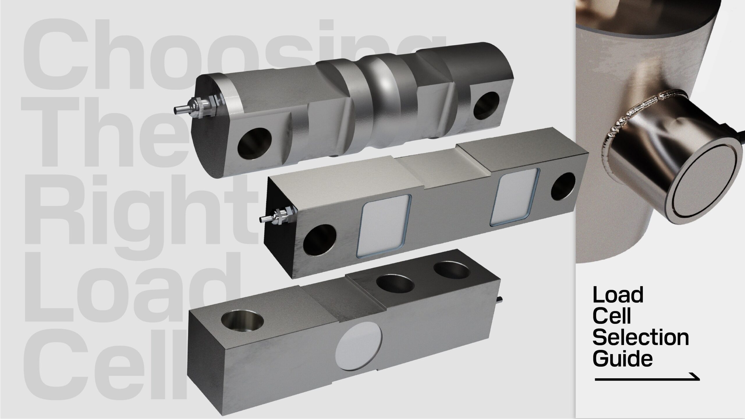
Load cells function by converting physical force into an electrical signal, a process that requires power and results in a signal output through the load cell’s cable. This cable is the lifeline of the load cell, typically comprising multiple coloured wires encased in a protective sheath. Its primary role is to connect the load cell to an external device, such as a junction box, digital indicator, or other instrumentation, facilitating both the supply of power to the load cell and the transmission of measurement data for processing and display.
Standard load cells typically present an analog signal output, ending in open cable wires, ready for integration into broader measurement systems. These open-ended cables allow for flexibility in connection but require a basic understanding of electrical wiring to ensure proper setup.
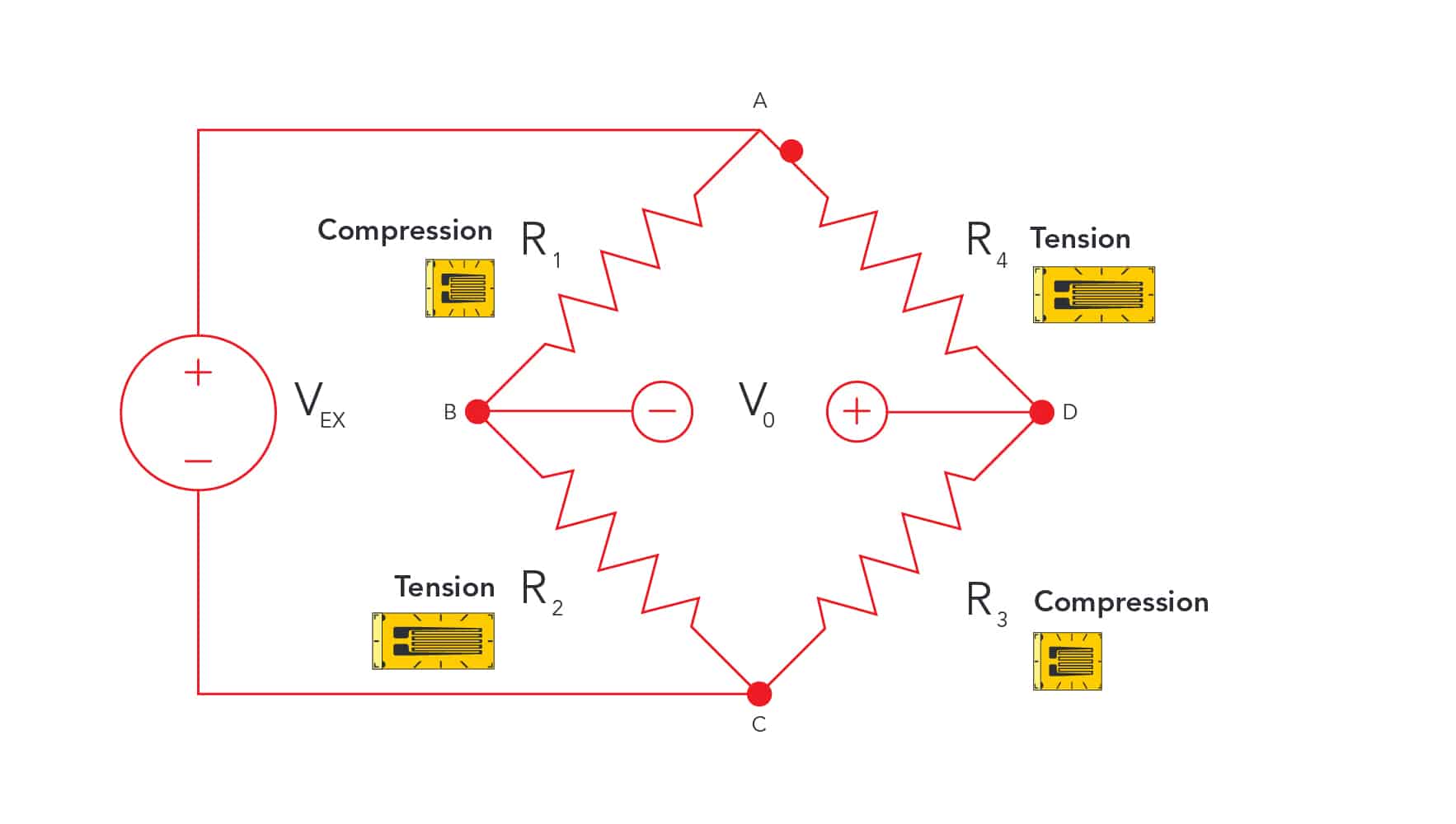
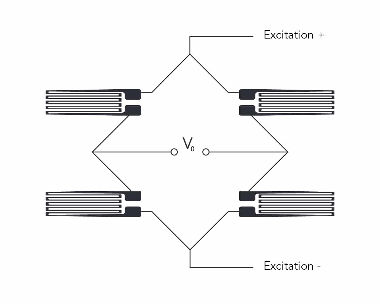
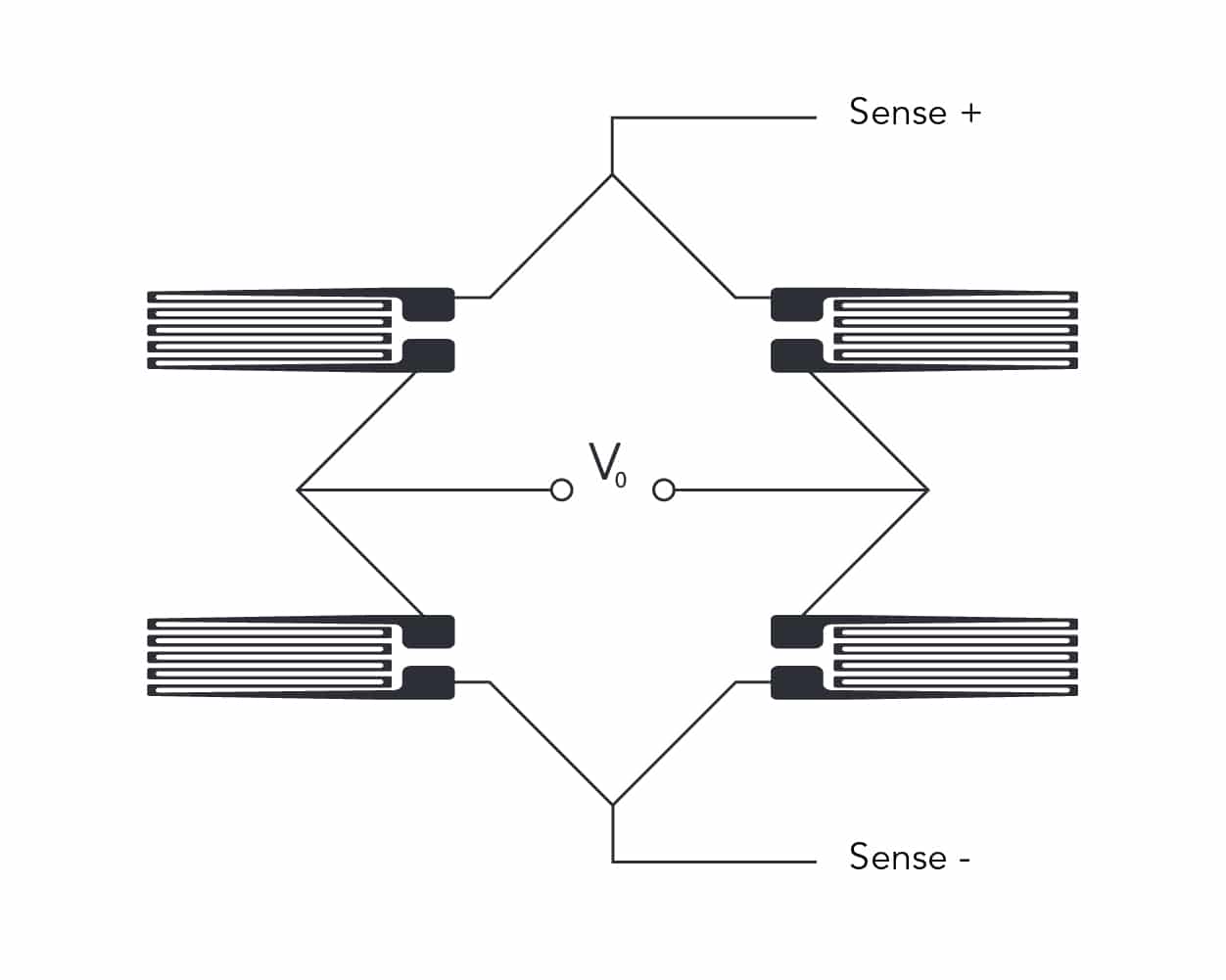
These cables typically house two pairs of wires vital for a load cell’s functionality: the excitation and signal wires. The excitation wires are responsible for powering the Wheatstone bridge circuit within the load cell, while the signal wires convey the electrical output resulting from mechanical strain. In certain cases, sense wires may also be included, although they are not critical in the majority of standard load cell applications.
NOTE: Some load cells may feature specialized connectors for specific applications or environments. Altering or interfacing with these connectors without detailed knowledge or manufacturer’s instructions can risk the load cell’s integrity and functionality.
2. Anatomy of Load Cell Cables
Load cell cables are designed to withstand the rigors of industrial environments, typically encased in a durable rubber or PVC sheath that protects the internal wires from physical and environmental damage. Inside this protective outer layer, there are 4 to 6 multi-coloured wires, each serving a specific function within the load cell. These wires are shielded to guard against electromagnetic interference.
From a practical standpoint, when connecting a load cell, it’s imperative to ensure proper metal-to-metal contact between the wire ends and the terminal or device they’re being connected to. This means stripping the insulation carefully to expose enough of the conductor for a secure connection, without damaging the wire itself. A good connection is crucial for the reliable transmission of power and signals; a loose or poor connection can result in inaccurate readings or intermittent signal loss. It is also advisable to use the appropriate connectors and follow the wiring colour codes specified by the manufacturer to avoid wiring errors that could lead to malfunction or damage to the load cell.
NOTE: Wiring color codes can differ between manufacturers. Always be sure to refer to the specific datasheet or calibration certificate of the load cell that you are working with.
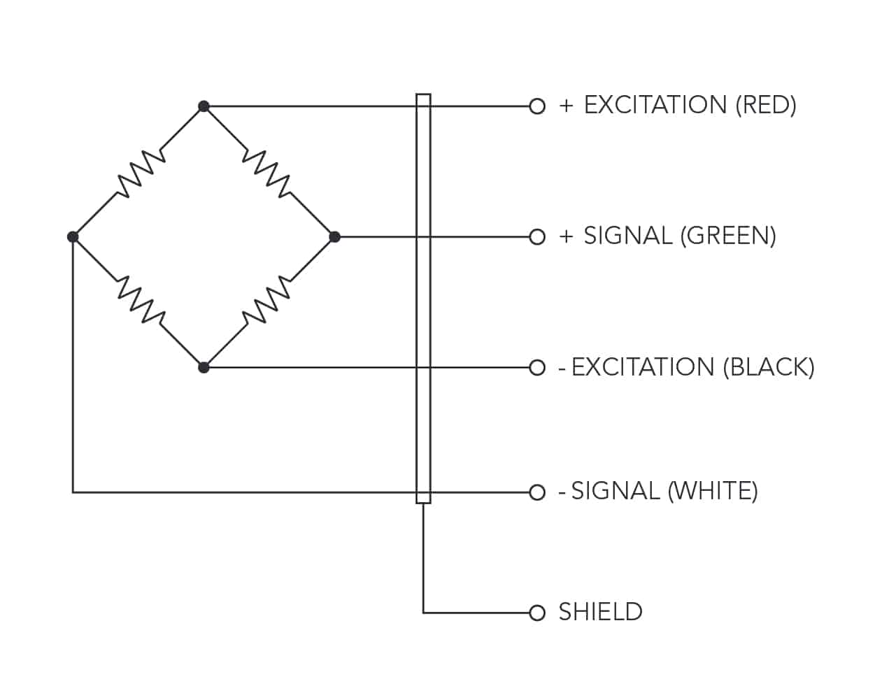
3. Excitation Wires
Excitation wires play a crucial role in the functionality of load cells by providing the electrical energy needed for the Wheatstone bridge circuit to operate. Typically, a load cell requires a stable and precise excitation voltage to ensure accurate force or weight measurements. The consistency of this power supply is key, as fluctuations can lead to variations in the output signal, affecting the reliability of the measurements.
5-10V is the typical excitation delivered to most load cells.
Excitation + (abbrev: VCC or EXC+)
Excitation – (abbrev: GND or EXC-)
4. Signal Wires
Signal wires within a load cell cable are essential for transmitting the electrical signals generated by the strain gauges as they respond to mechanical forces. These wires carry the analog signals that represent the precise measurements of weight or force from the load cell to the readout indicator or data acquisition system.
Analogue load cell signals are generally measured as a fraction of the excitation voltage being delivered. This is referred to as the load cell’s signal output and is denoted in millivolts per volt (mV/V).
Most standard load cells in the weighing industry are 2.0mV/V or 3.0mV/V.
Signal + (abbrev: OUT+ or SIG+)
Signal – (abbrev: OUT- or SIG-)
5. Sense Wires
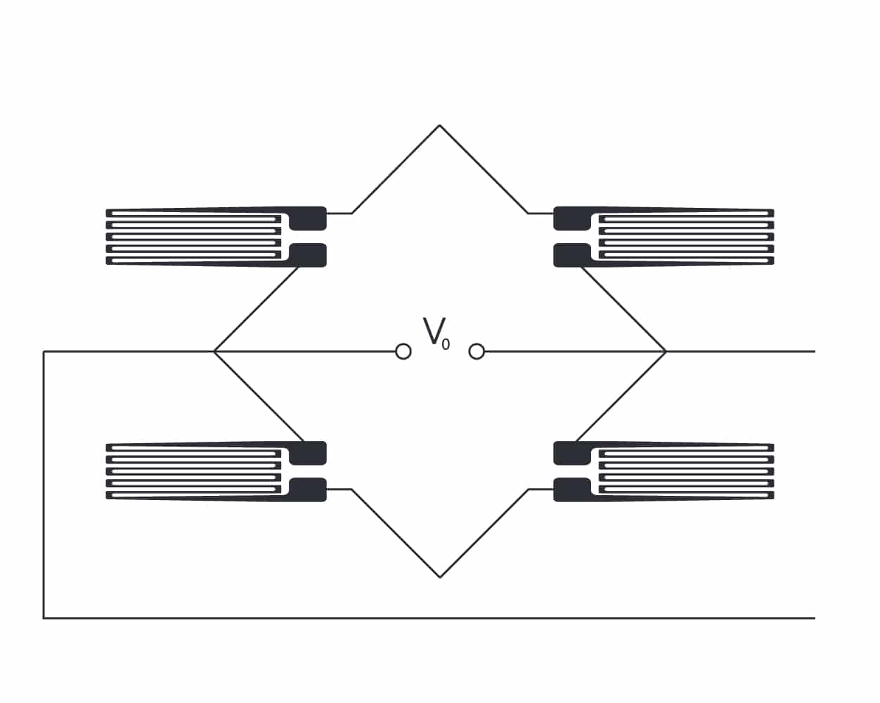
Sense wires in load cell systems enhance accuracy in scenarios with extended cable lengths or where very significant temperature shifts can affect performance. Often included in 6-wire configurations, these wires create a feedback mechanism for the excitation voltage, compensating for resistance changes in signal and excitation wires due to varying cable lengths (>20m or 65ft).
Connected to the load cell’s excitation and signal terminals on the instrument side, sense wires allow for real-time adjustments to the voltage at the load cell, stabilizing the excitation voltage.
However, for most applications, sense wires are unnecessary. Load cells are typically calibrated to standard cable lengths during manufacturing, and in practical settings, they are usually linked to a junction box, from which any long-distance cabling extends. Since junction boxes include sense wire connections, the direct long-distance wiring of a single load cell exceeding 20m (65ft) is very rare.
EXAMPLE: If an indicator delivering 10V to the load cell, generates a return signal of 2.0 mV/V, a drop in the actual excitation voltage reaching the load cell over a 30m distance down to 9.98V could compromise the measurement accuracy
6. Shielding
The shield within a load cell cable acts as a barrier against electromagnetic (EMI) or radio-frequency interference, which can distort the analog signals of a load cell. It is typically a conductive layer of braided copper or aluminum foil, that encases the inner wires.
The shield is grounded at one end, usually at the point of signal interpretation or data acquisition, creating a path for any intercepted interference to be safely diverted. This grounding is essential in maintaining the clarity and accuracy of the measurements by preventing noise from contaminating the signal. Proper installation and grounding of the shield are key to ensuring the effectiveness of this protective layer, especially in electrically noisy industrial environments.
7. Connection Load Cell Wires
Connecting Load Cell Wires to Terminals
Ensuring a secure connection of load cell wires to the terminals of a junction box, indicator, or data acquisition system is crucial for the accurate transmission of signals. Firstly, identify each wire within the load cell cable based on its designated function and color coding — typically including excitation (+ and -), signal (+ and -), and potentially sense (+ and -) wires. Always refer to the load cell’s specific wiring diagram to accurately match each wire to its corresponding terminal.
Each wire should then be securely fastened to its respective terminal within the junction box or indicator. Terminals are often clearly labelled with “+/-” signs for excitation and signal connections, and possibly separate inputs for sense wires if applicable.
The bare wire should be in full contact with the terminal, held tightly by screws or clamps, ensuring a stable electrical pathway. This is vital to prevent any signal loss, resistance increase, or intermittent connections that could lead to inaccurate readings. In environments prone to vibration or movement, consider using locking washers or thread-locking fluid to prevent connections from loosening over time.