


Strain Gauge
Last Updated On • 10 min read
1. What is a Strain Gauge?
Strain gauges are a type of variable resistors used to measure mechanical deformation—specifically, the strain of an object. It works by measuring the change in electrical resistance of a material when it is subjected to mechanical stress. Consisting primarily of a metallic conductor wire or foil applied onto a flexible backing film, strains lead to the conductor being stretched, causing electrical resistance to change. This change in resistance can be precisely measured using a Wheatstone Bridge circuit.
If load cell sensors are the “nervous system” of industrial equipment, strain gauges are the “nerves” of individual load cells. Understanding what a strain gauge is and its properties and attributes are critical when working with load cells and other force measurement sensing systems.
2. The Anatomy of a Strain Gauge
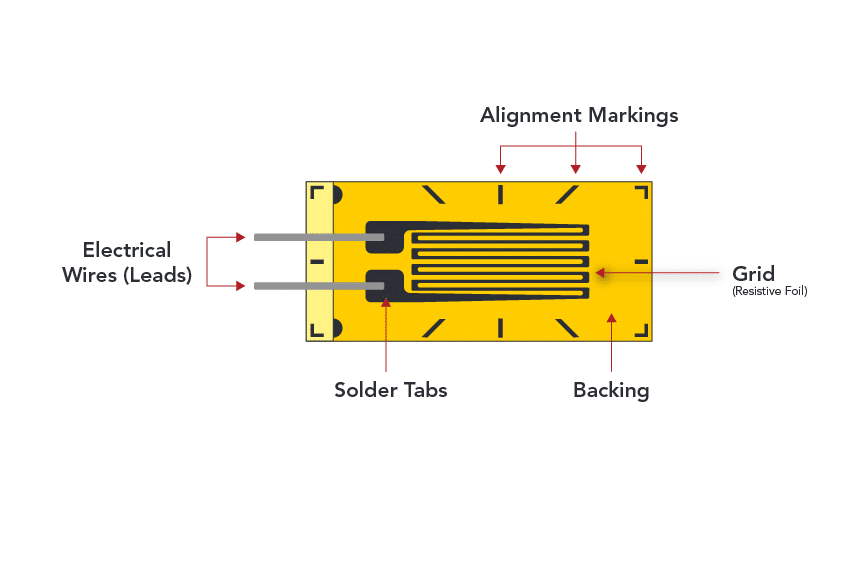
Strain gauges consist of a very thin conductive wire arranged in a grid pattern that is bonded to the surface of a non-conductive, flexible backing foil. When this backing material is strained, the measuring grid is also stretched, which causes its electrical resistance to change.
Measuring Grid (Conductive Wire): The conductive metallic foil typically made of constantan wire (a copper-nickel alloy) that is arranged in a grid pattern. This is the active component that varies in electrical resistance depending on how it is deformed.
Backing foil (Carrier): The layer of non-conductive material that the grid is affixed onto. Polyimide is a commonly used material due to its durability and flexibility.
Covering Layer: A protective layer or coating applied over the grid may exist on some strain gauges to help shield the gauge from environmental factors.
Lead Wires: Connected to the ends of the metallic pattern at the solder tabs, serving as the conduit for electrical currents to and from the grid.
Alignment Markings: Visible markings on the strain gauge that aid in its precise alignment when being applied to the surface of an object.
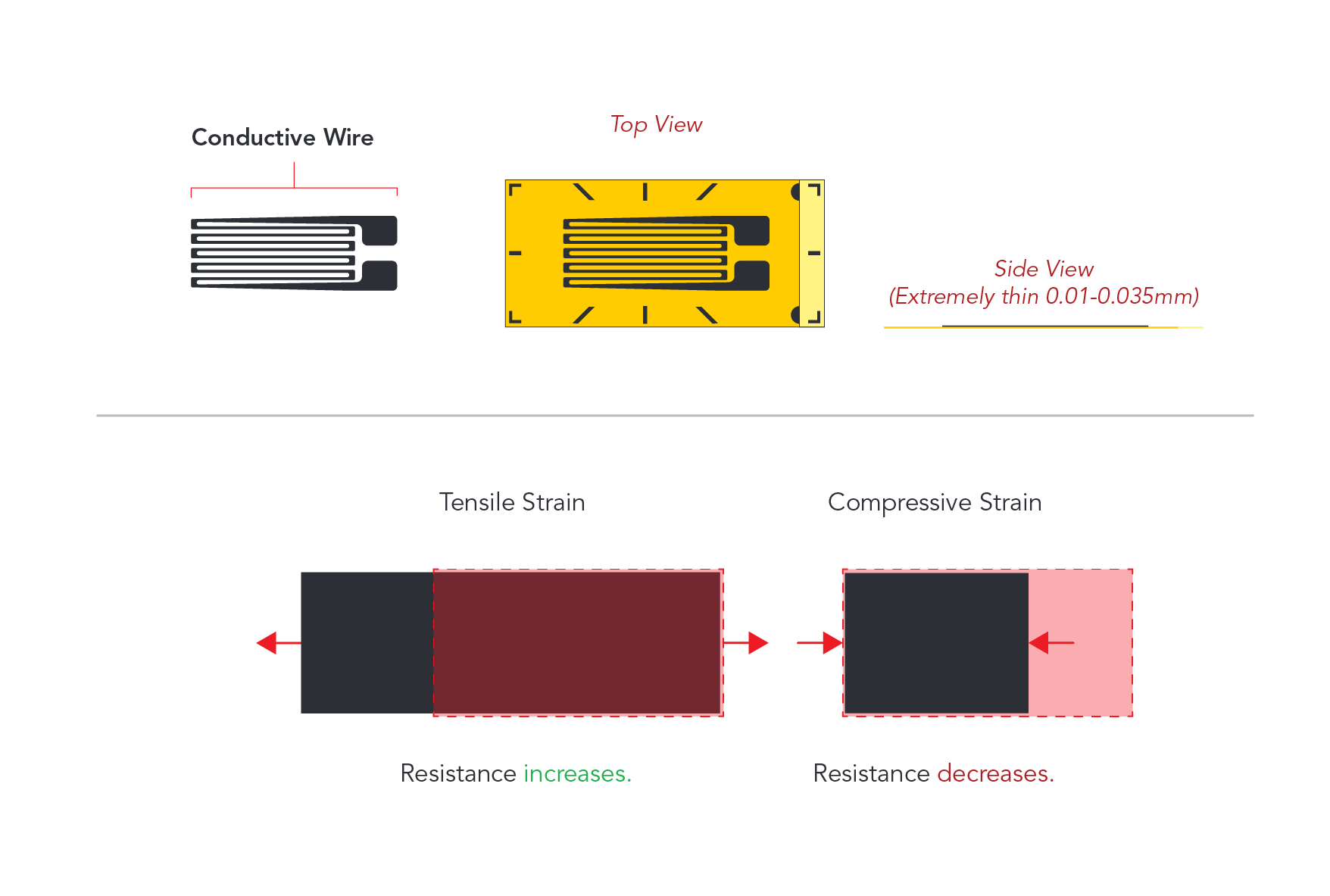
Strain gauges resemble a very thin film and are generally very small in size—a fraction of the size of postage stamps. They can take a variety of shapes depending on the force that needs to be measured and other factors. Despite their versatility, strain gauges are delicate sensors vulnerable to environmental exposure (moisture, physical damage, corrosion, etc.). Their accuracy and reliability is significantly enhanced when integrated within load cell technology.
3. Principles of Operation
Strain gauges consist of a conductive wire that is bonded to the surface of a flexible backing material. When this backing material is strained, the conductive wire is also stretched, which causes its electrical resistance to change.
The relationship between the change in resistance (∆R) of a strain gauge and the strain (ε) experienced by the gauge’s measuring grid due to an applied load is crucial for understanding how strain gauges work. This relationship is typically linear within the material’s elastic limit, meaning the conductive grid returns to its original shape and size once the load is removed.
The proportionality between the resistance change and the strain is defined by the gauge factor (GF), also sometimes referred to as the “k-factor,” expressed as:

Where:
– (GF) is the gauge factor, a dimensionless number.
– (∆R) is the change in resistance caused by strain.
– (R) is the initial resistance of the strain gauge.
– (ε) is the strain, defined as the deformation per unit length ( ε = ∆L / L ), where (∆L) is the change in length and (∆L) is the original length.
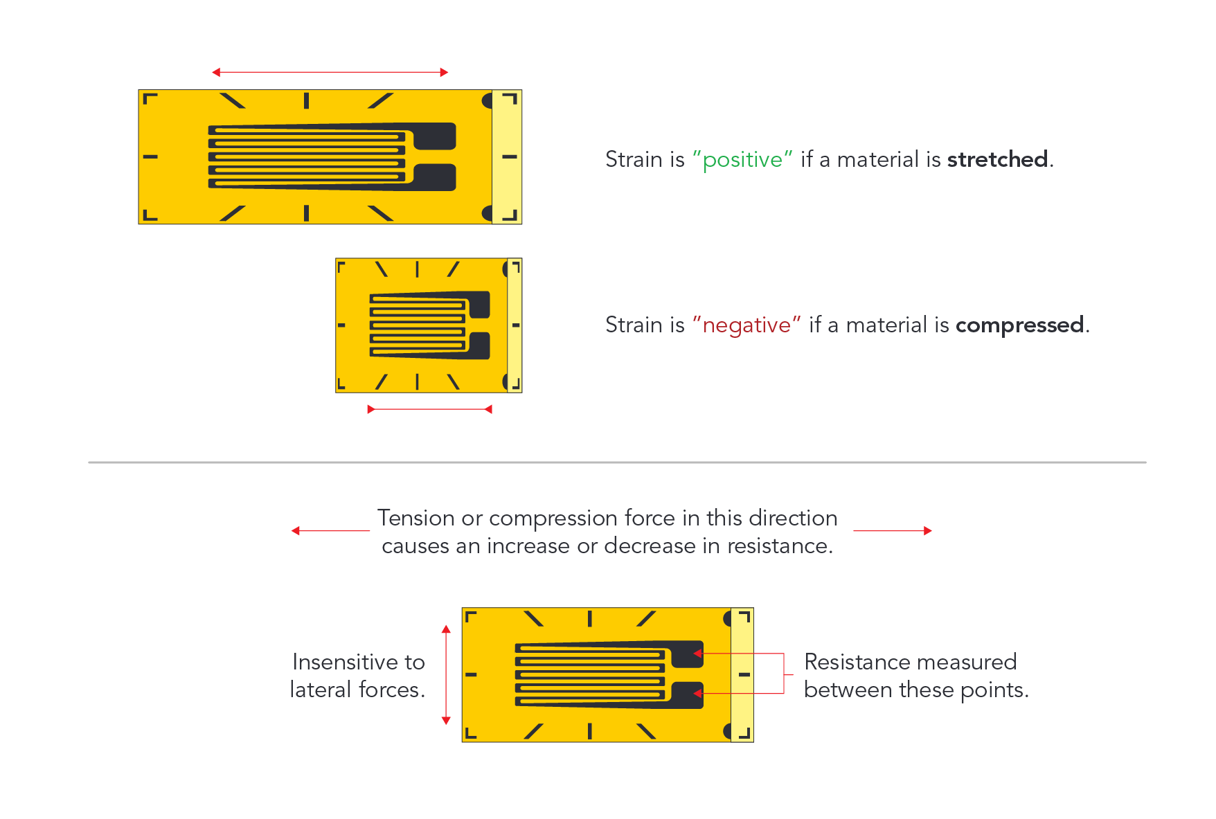
In practical terms, when a load is applied to a structure with an attached strain gauge, it causes the gauge (and its conductive wire) to deform. This deformation alters the length and cross-sectional area of the conductive path, thereby changing its electrical resistance. The gauge factor (GF) quantifies how sensitive the strain gauge is to this strain-induced change in resistance.
This linear relationship between resistance change and strain underlies the strain gauge’s functionality. As the resistance changes, so does the voltage drop across the gauge when a constant current is passed through it. This change in voltage is proportional to the change in resistance (Ohm’s Law: V = IR ), and thus to the strain. In a strain gauge load cell, this voltage change is measured, often using a Wheatstone bridge circuit to amplify the signal and improve measurement precision. The output voltage from the bridge provides a direct, quantifiable measure of the applied load, based on the known relationship encapsulated by the gauge factor (GF).
The gauge factor is crucial for calibrating strain gauge systems and interpreting their output since it directly relates the physical strain on the material to the electrical signal measured by the instrumentation.
4. Strain Gauge Applications
Strain gauges are versatile sensors found in a variety of applications where precise measurement of mechanical deformation is crucial. From the aerospace industry, where they monitor stress on aircraft components, to civil engineering projects assessing structural integrity of bridges and buildings, strain gauges provide essential data for safety and design optimization.

Strain gauges can effectively measure any mechanical forces that cause strain (deformation) within a material:
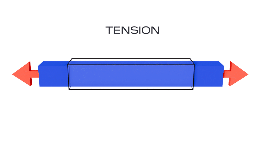
1. Tension: This is a pulling force that stretches material. Strain gauges can measure tension by detecting the elongation in the material, which causes an increase in the gauge’s electrical resistance.
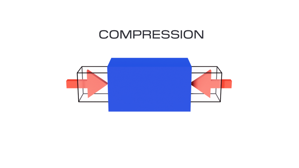
2. Compression: The opposite of tension, compression involves a pushing force that compacts or squeezes material. Strain gauges measure compression by sensing a decrease in the material’s length and an associated decrease in electrical resistance.
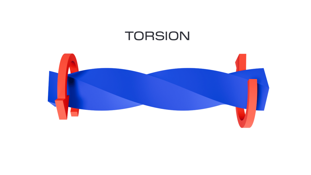
3. Torque: This rotational force causes twisting in a material. Strain gauges measure torsion by being positioned in such a way that they detect the shear strain resulting from the twisting action, altering the gauge’s resistance.
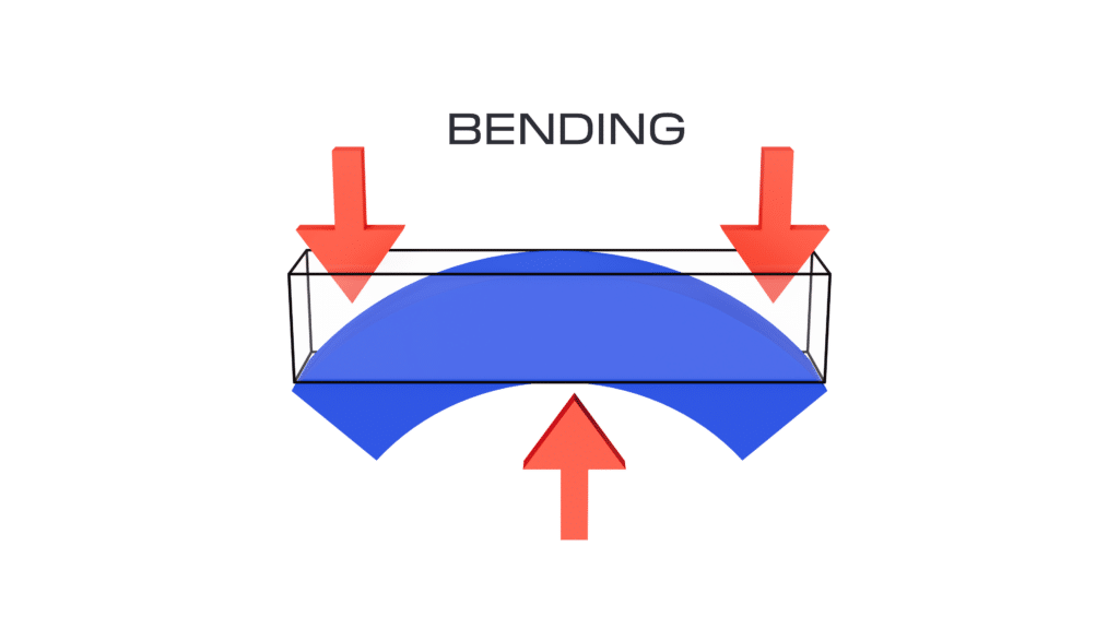
4. Bending: This force causes material to curve or flex. Strain gauges placed on the surface of a bending beam, for example, can measure bending forces by detecting tensile strain on the outer side of the bend and compressive strain on the inner side.
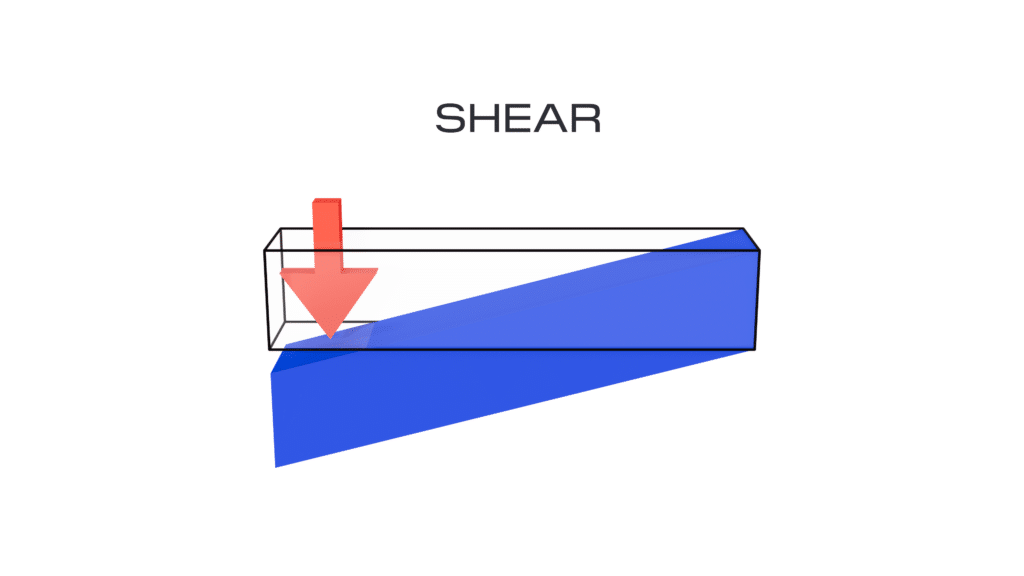
5. Shear: This force causes parts of a material to slide past one another. Shear strain gauges are specially oriented to measure the change in resistance due to this sliding action.
5. Strain Gauges in Load Cells
Strain gauges are inherently susceptible to environmental factors such as moisture, corrosion, and physical damage, which can compromise their accuracy and longevity. To mitigate these vulnerabilities and enhance accuracy of measurements, strain gauges are encapsulated within load cells and configured in Wheatstone bridge circuits. This not only protects them from environmental damage but also leverages 1) the bridge circuit’s ability to compensate for temperature fluctuations and electrical noise, ensuring precise and stable readings and 2) the metal element’s ability to reject unwanted applied loads.
Within load cells, strain gauges are meticulously integrated to capture the slightest deformations caused by applied loads, converting mechanical forces into electrical signals. The gauges are precisely bonded to the load cell element. This element is designed to deform under load, and the deformation is precisely measured by the strain gauges. The performance of the strain gauge depends critically on the meticulous care and precision involved in its manufacturing process, which is similar in many regards to semiconductor fabrication.
To amplify and accurately measure the small changes in resistance from the strain gauges, load cells often employ Wheatstone bridge circuits. This arrangement enhances the sensitivity and accuracy of measurements, making it an essential topic for further exploration in our dedicated article on Wheatstone bridge circuits.