

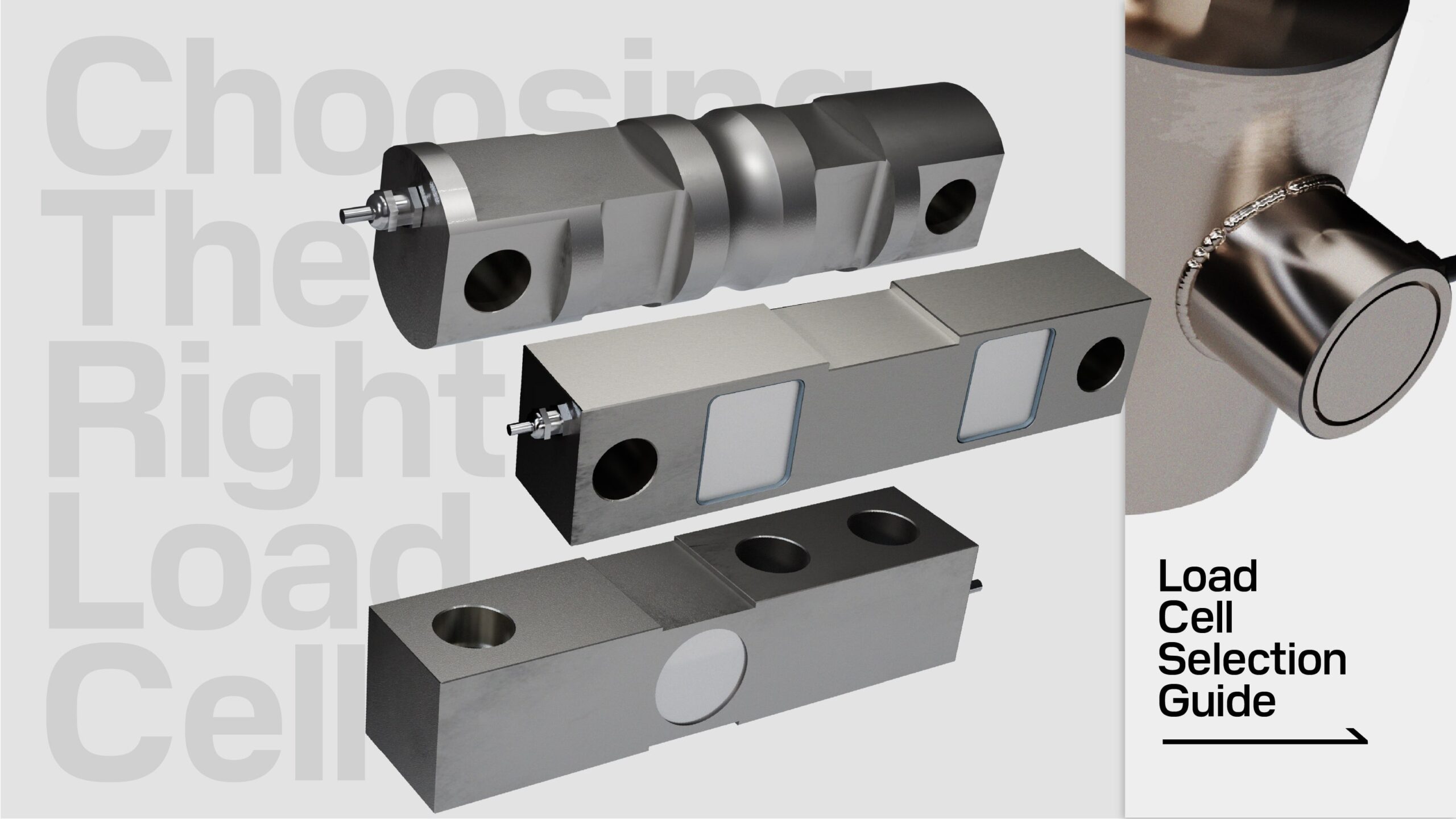
Common Types of Load Cells
Last Updated On • 10 min read
Understanding the diverse range of load cell designs is essential when choosing the perfect fit for specific applications. From single-point to s-type, and from single-ended beams to double-ended beams, canister, planar beams, to tension links, each type of load cell offers unique benefits and potential limitations tailored to distinct measuring scenarios. When selecting the best type of load cell for a particular application, it is helpful to understand some key factors that can inform the selection and design process.
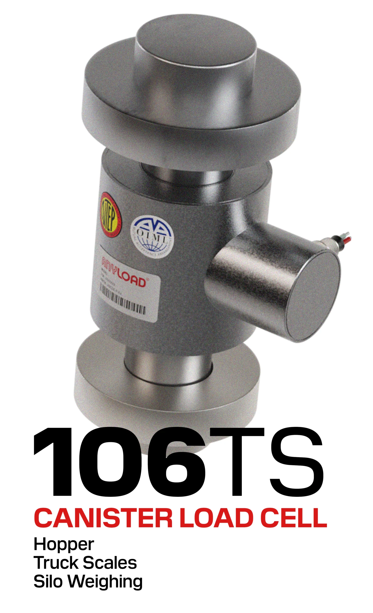
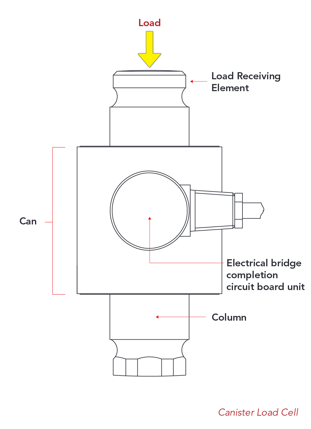
1. Canister Load Cells
A canister load cell (also referred to as a rocker pin or a column load cell) is a cylindrical-shaped force transducer designed to measure compressive loads often in higher-capacity weighing applications typically exceeding 10,000lbs. The loading force passes vertically through the top and bottom. A central sensing section flexes slightly under pressure, and this deformation is measured by strain gauges that convert the momentary deformation into an electrical signal. The sensing section is enclosed within a housing tube that protects it from physical and moisture damage.
The relatively simple design is resistant to bending and sideloading forces, ensuring accurate measurements even in multi-directional force environments.
Application Notes:
- Canister load cells without top or bottom threads (referred to as a “rocker column” or “rocker pin” load cell) allow for better side load protection, minimized bending and torque force interreference.
- In truck scale applications, canisters are susceptible to twisting, toppling, and general wear-and-tear but is a more economical design as compared to the double-ended shear beam.
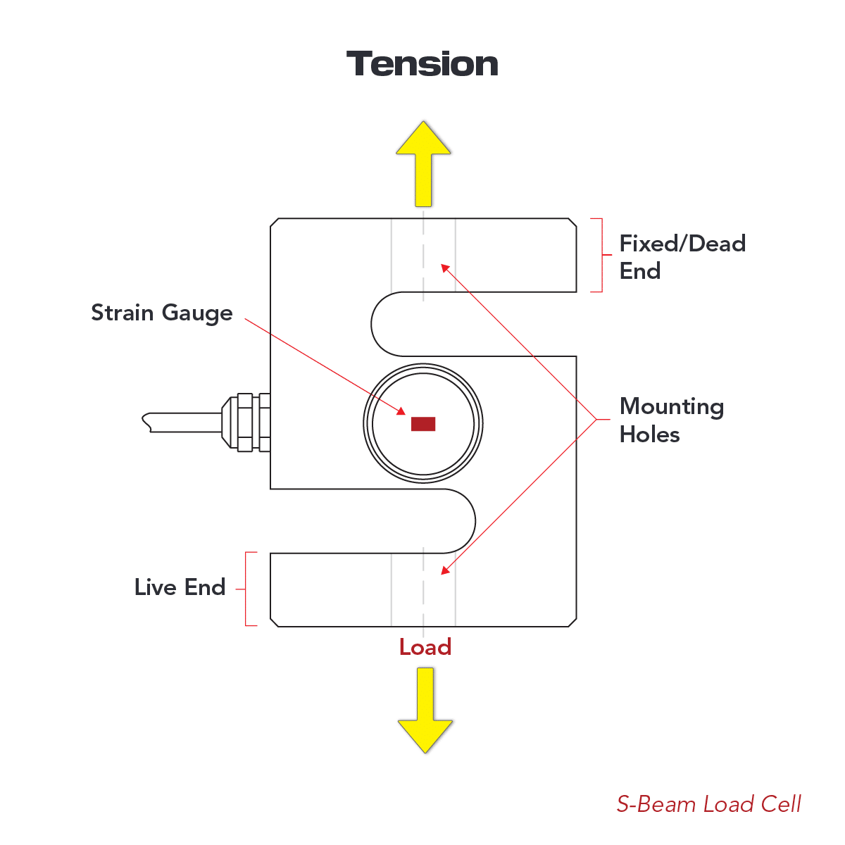
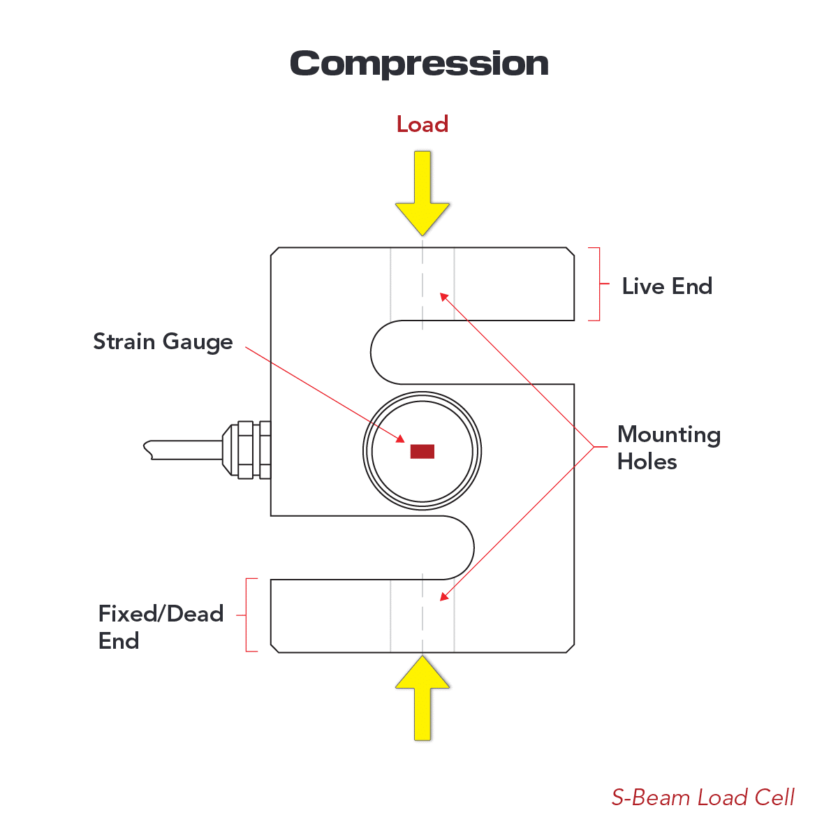
2. S-Beam Load Cells
S-beam load cells (also referred to as S-type load cells) are economical, high-accuracy load cells able to measure both tension and compression forces in low to medium capacity applications. Top and bottom threaded through-holes allow for easy installation in suspended tension weighing or to receive compression loads.
The S-beam design provides excellent side load rejection. For best performance, the load should be applied without factors such as bending or torque force, and the load cell is paired with rod-end bearings or tension weigh modules. S-beam load cells are often used to suspend a weigh vessel, applying tension through stretching (Fig 2.1). Common applications of the S-beam include crane scales, hopper scales, tension-compression force measurement, and test machines.
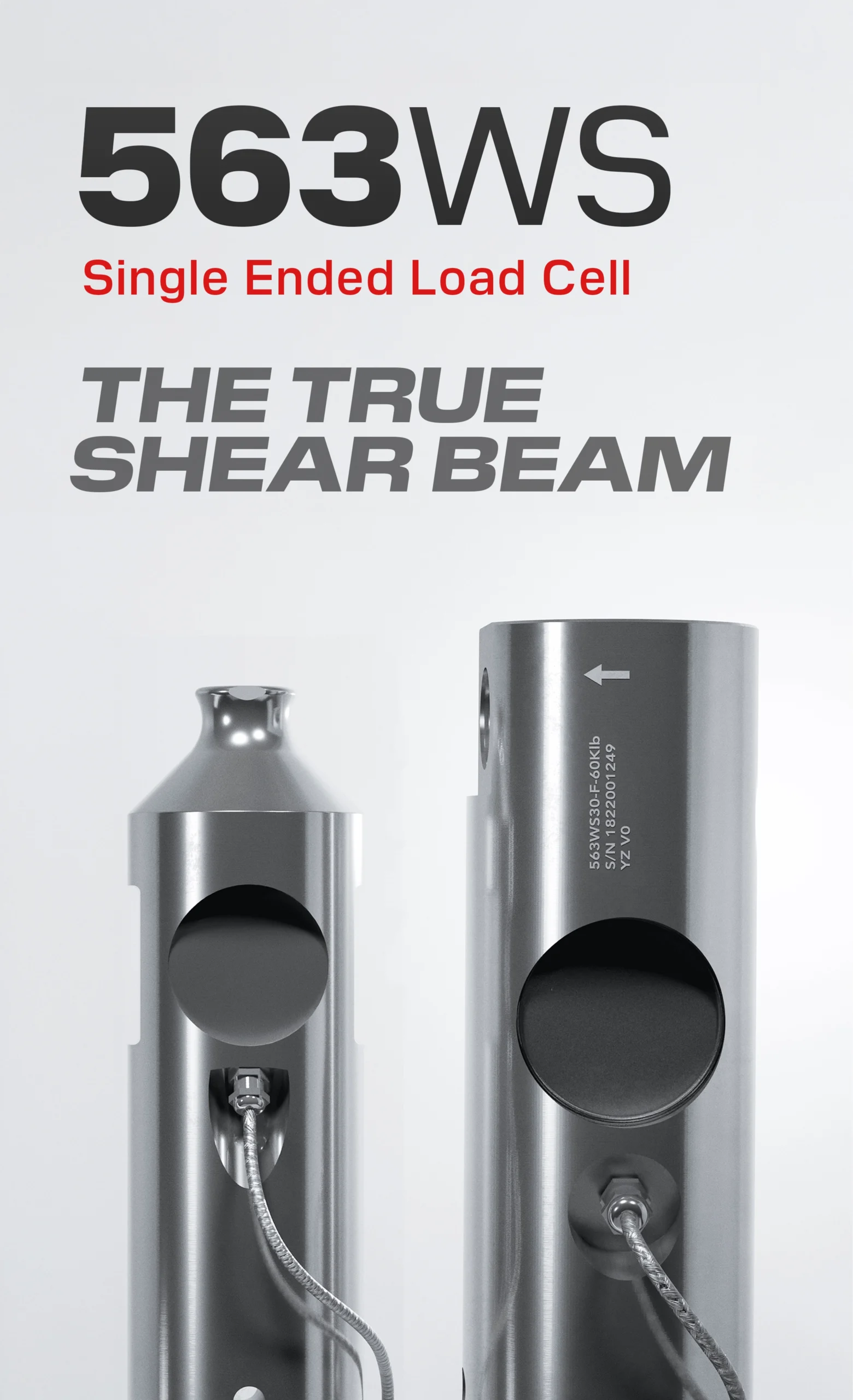
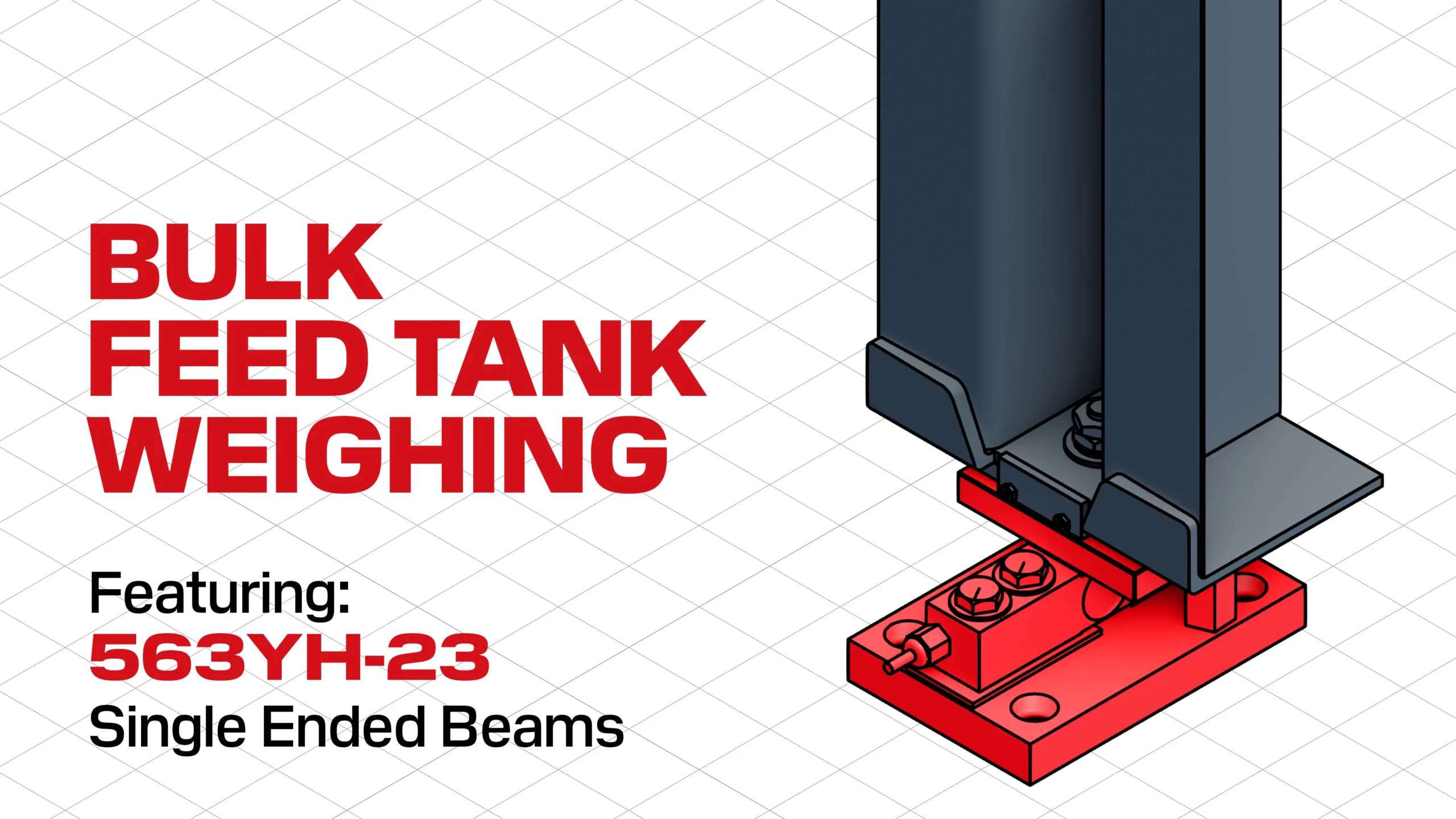
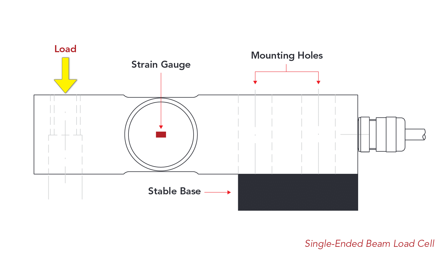
3. Single-Ended Beam Load Cells
In bending beam load cells, strain gauges of the sensing section are strategically placed inside a through-hole, allowing for accurate measurements of bending forces as the beam deforms elastically. This design makes them an economical option for lighter capacity weighing applications typically under ~1,500lbs.
True shear beam load cells are recognized for the blind hole internal structure of their sensing section with a centre web that precisely measures shear forces. This specialized design more effectively cancels out torque and off-centre loads, minimizing errors while its stronger H-beam structure makes them better suited for higher-capacity weighing up to ~75,000lbs.
Application Notes:
- The platform size that a single point load cell is used in should not exceed the recommended specifications provided by the manufacturer. Exceeding the specified platter size can result in diminished off-centre load accuracy and legal-for-trade compliance issues.
- Corner error can be further reduced by filling the dog-bone shaped sensing section. This is irreversible and must be done by a qualified professional familiar with this technique.
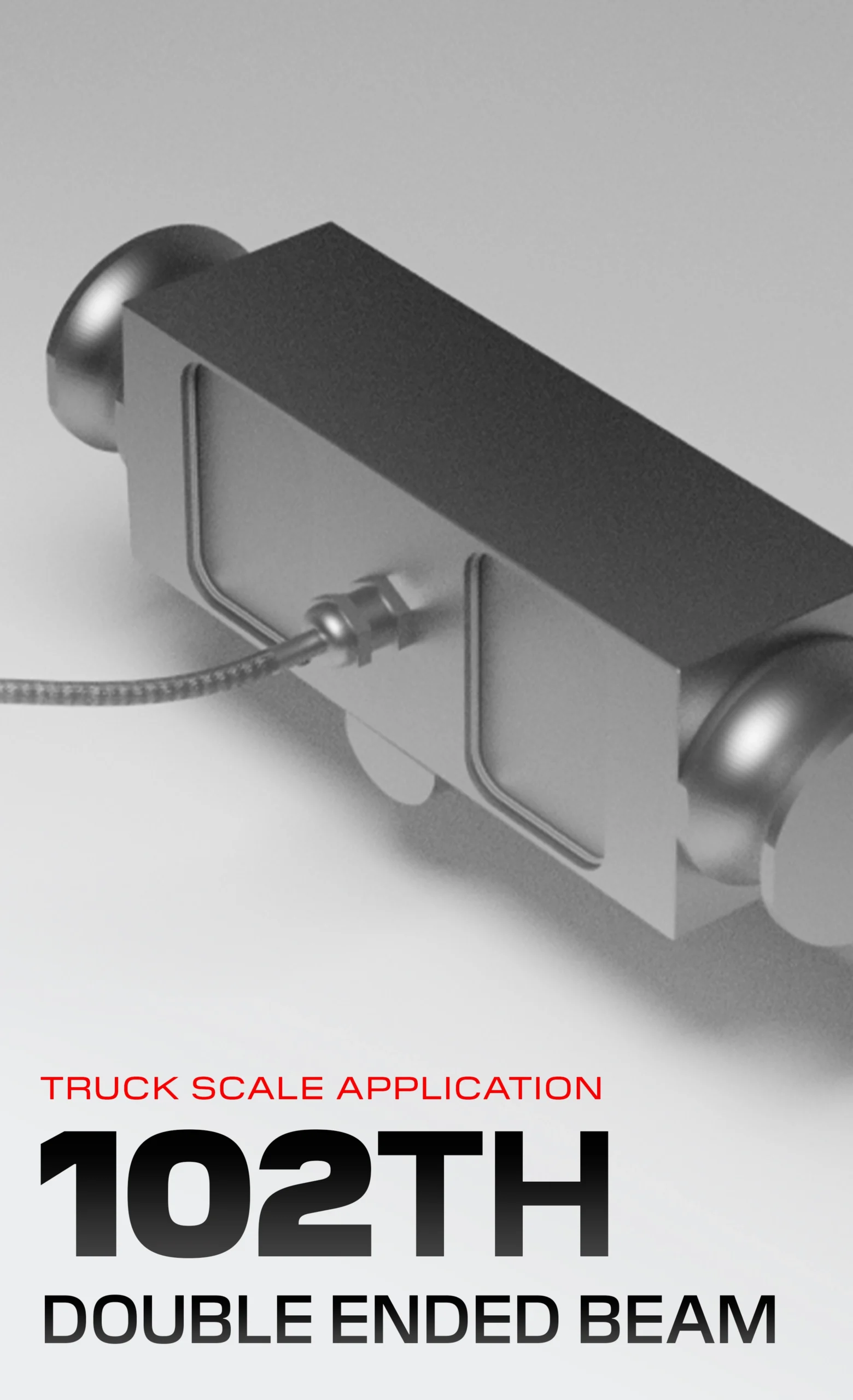
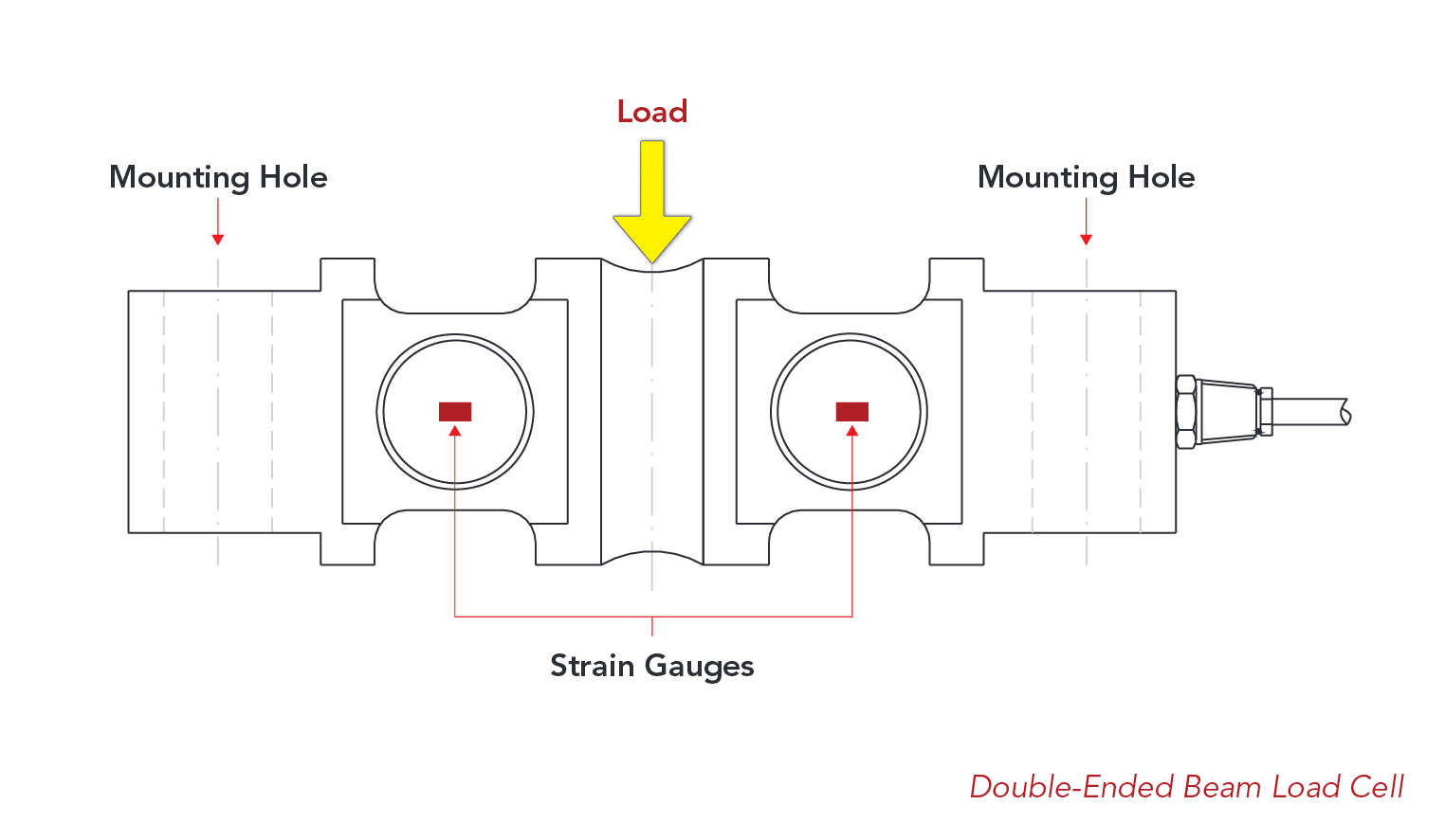
4. Double-Ended Shear Beam Load Cells
The double-ended shear beam is similar in design to the single-ended shear beam, with the centre web sensing section in the middle of the load cell. However, it is secured at both ends while force is exerted onto the centre of the beam structure. This type of load cell is commonly found in higher-capacity industrial weighing applications above ~5,000lbs such as in tank/silo weighing, truck scales, and other heavy vessel-weighing applications.
An advantage of the double-ended shear beam is its structural stability and reliability in harsh or more mobile applications, especially compared to canister load cells. Securing double-ended shear beams typically requires a less complex setup, as the load cell’s rigid rectangular structure and dual fixed points naturally resists shifting or tilting, maintaining precise measurement even in demanding conditions.
5. Single Point Load Cells
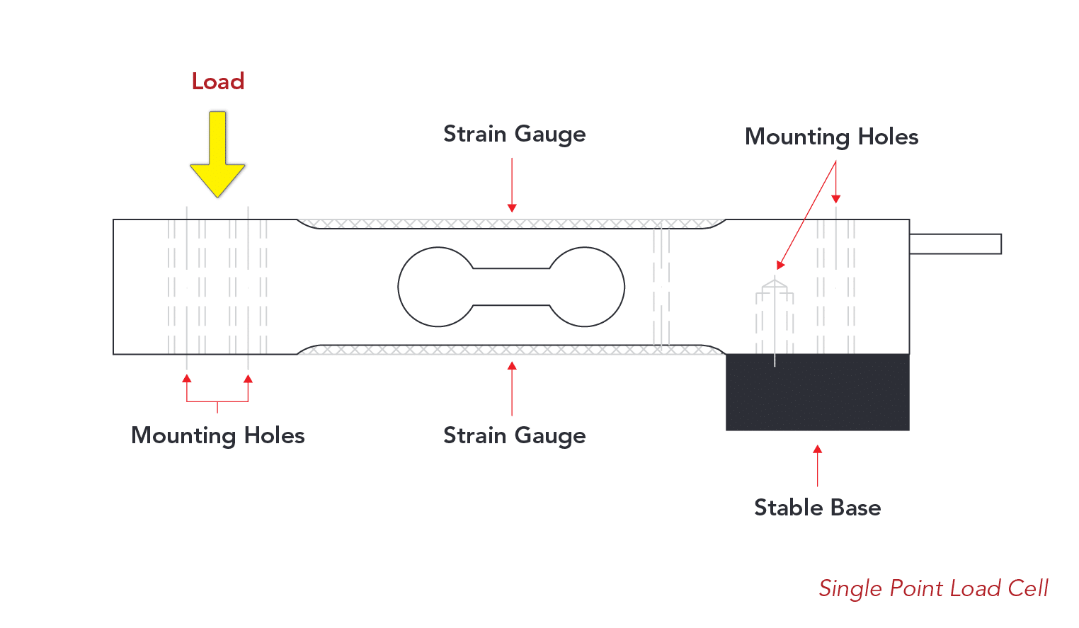
Single point load cells (also referred to as a platform load cell) are designed to measure compression force applied to a single point. A single point load cell can be installed underneath a platform, allowing for off-centre loading while maintaining accuracy. Loads can be applied anywhere on a platform and still result in consistent readings. The single point design is commonly found in lower capacity applications, particularly bench scales, and typically do not exceed 1,000lbs in rated capacity.
Did you know that ANYLOAD holds the world’s highest legal-for-trade certification for a load cell?
The 651-series is certified up to OIML C9.
Application Notes:
- Single point load cells should be installed with the loading area centred underneath the platform, NOT the load cell itself being centred.
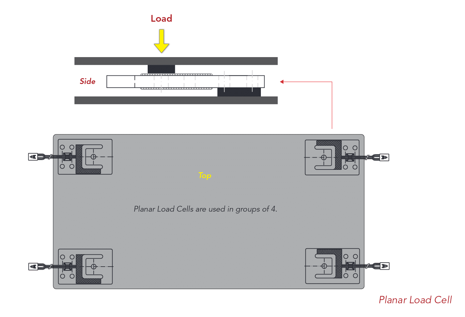
6. Planar Load Cells
Planar beam load cells are low-profile load cells designed for compression weighing in lower-capacity weighing applications under ~1,000lbs. They are characterized by a flat, load-bearing surface with strain gaugesapplied to the central area, where the most significant bending or flexing occurs when a load is applied. Its simplicity allows for planar load cells to be manufactured quite economically and are easy to integrate into postal scales, medical scales, and other compact systems where vertical space may be limited.
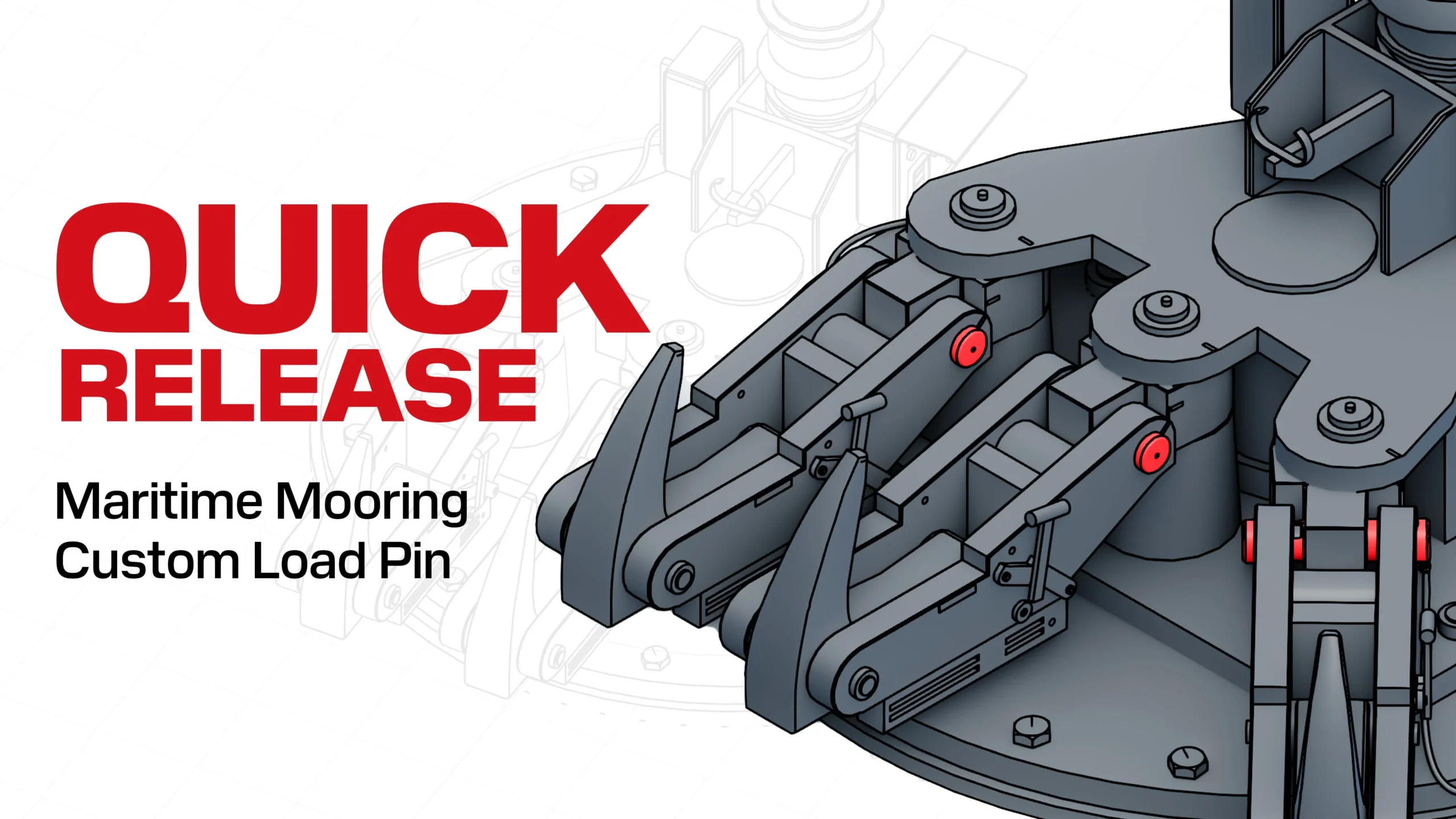
7. Load Pin Load Cells
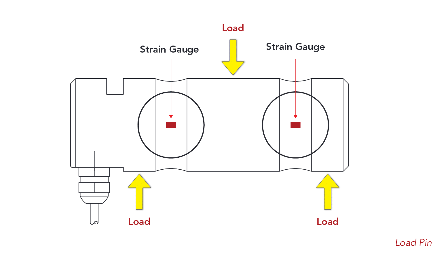
Load pins are designed for the measurement of tension or compression while directly integrated into the force flow without occupying additional space. Load pins can easily replace retention bolts or exles in existing applications. Since the design requirements are tailored to the situation, the exact dimensions of the load pin are critical.
Common applications are found across many industries, from steel mills, chemical plants, seaports, and logistics, anywhere where there are retention bolts or excels in existing applications usually for. Load pins are frequently used in providing safety checking for systems, and protection from overload, and are favoured wherever space restrictions and ease of integration are important.
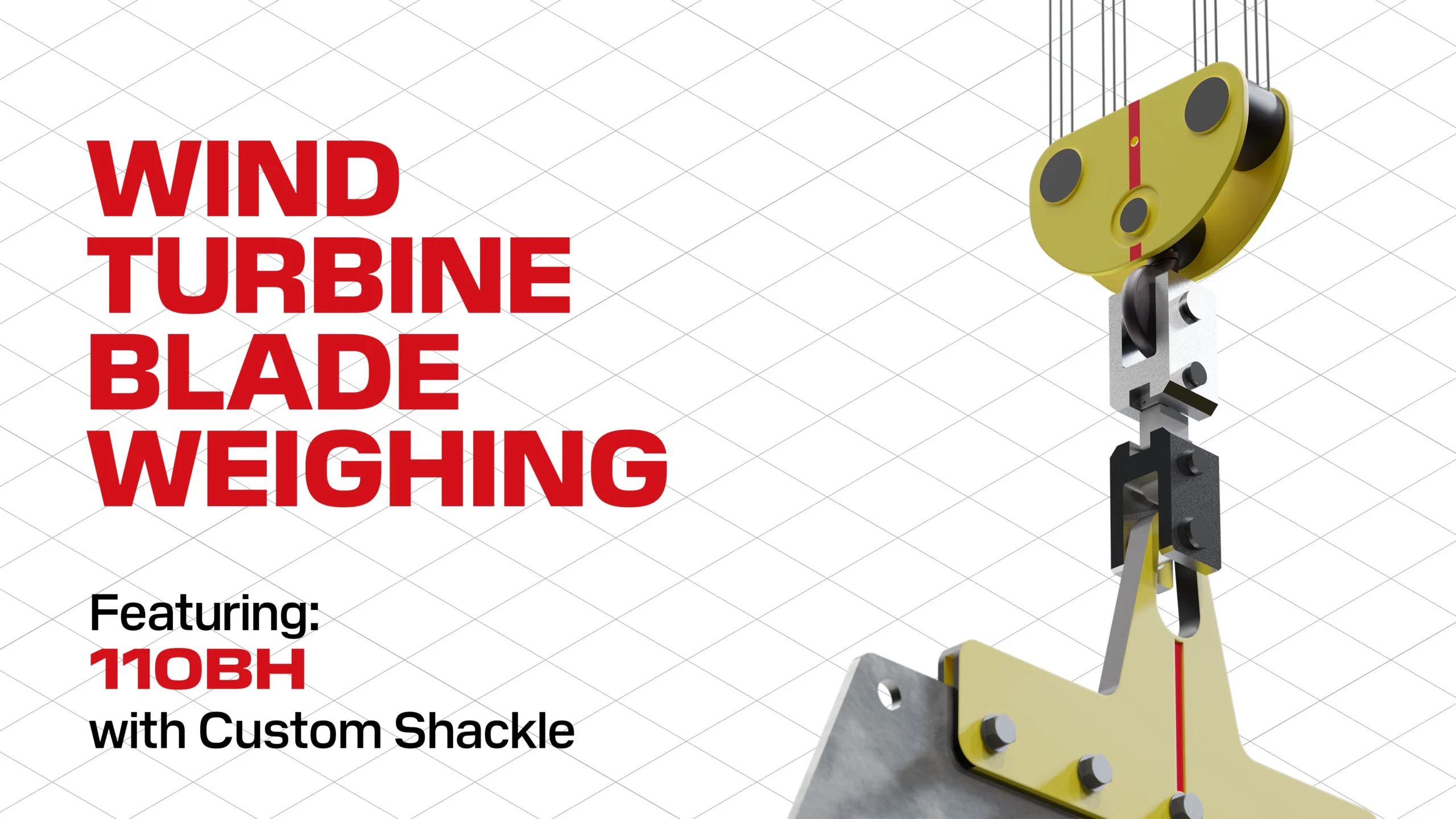
8. Tension Link Load Cells
Tension link load cells are designed to measure tension loads with two through-holes at its top and bottom, functioning and resembling similarly to S-beam load cells. The tension link is resistant to bending moment and torque and is well suited for heavy capacity applications typically exceeding ~2,500lbs, such as in heavy-duty crane scales, industrial cranes and rigging, and more.
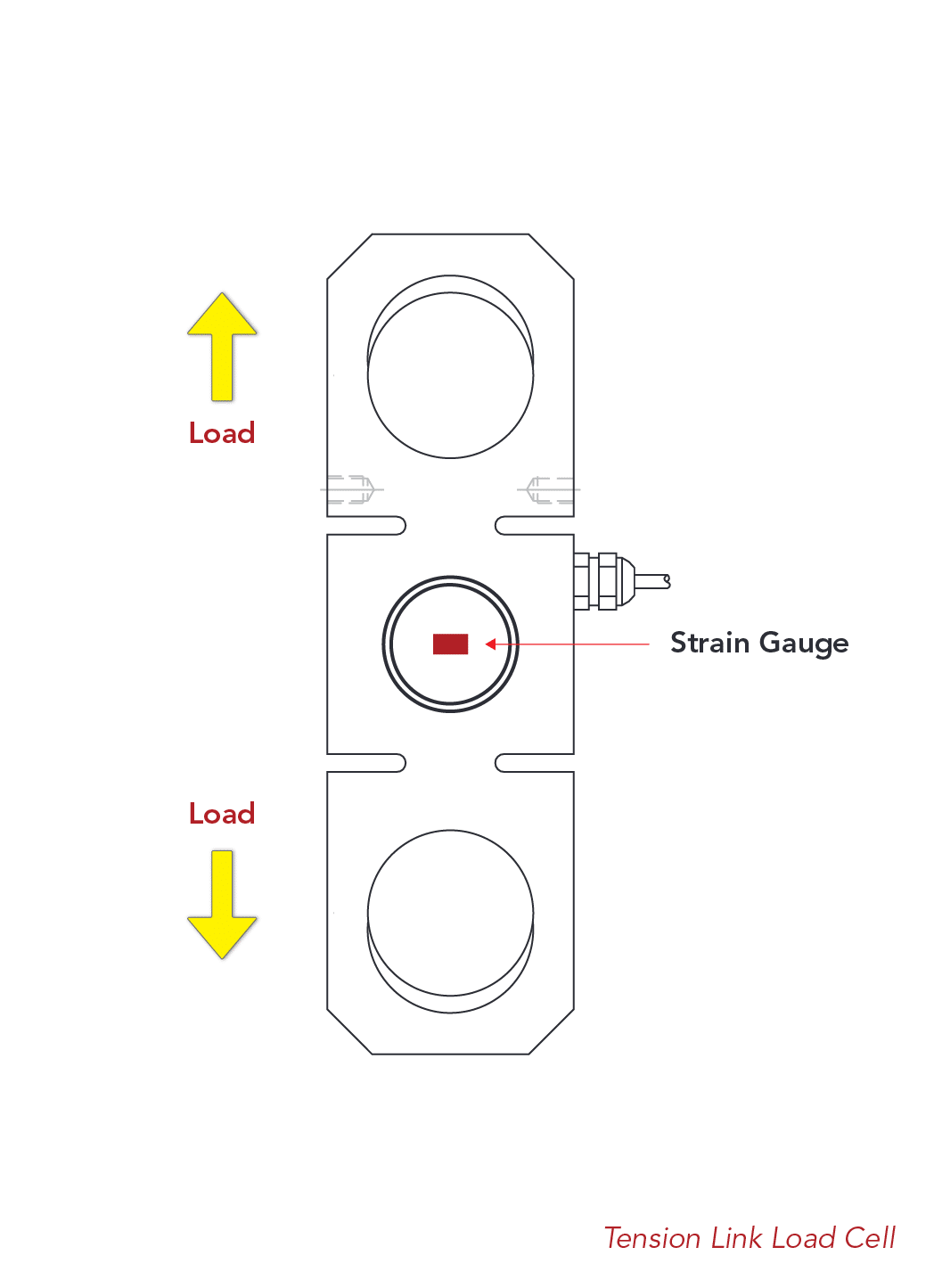
Did you know that ANYLOAD holds the world’s highest legal-for-trade certification for a tension link load cell?
The 110-series tension links are certified up to OIML C6.
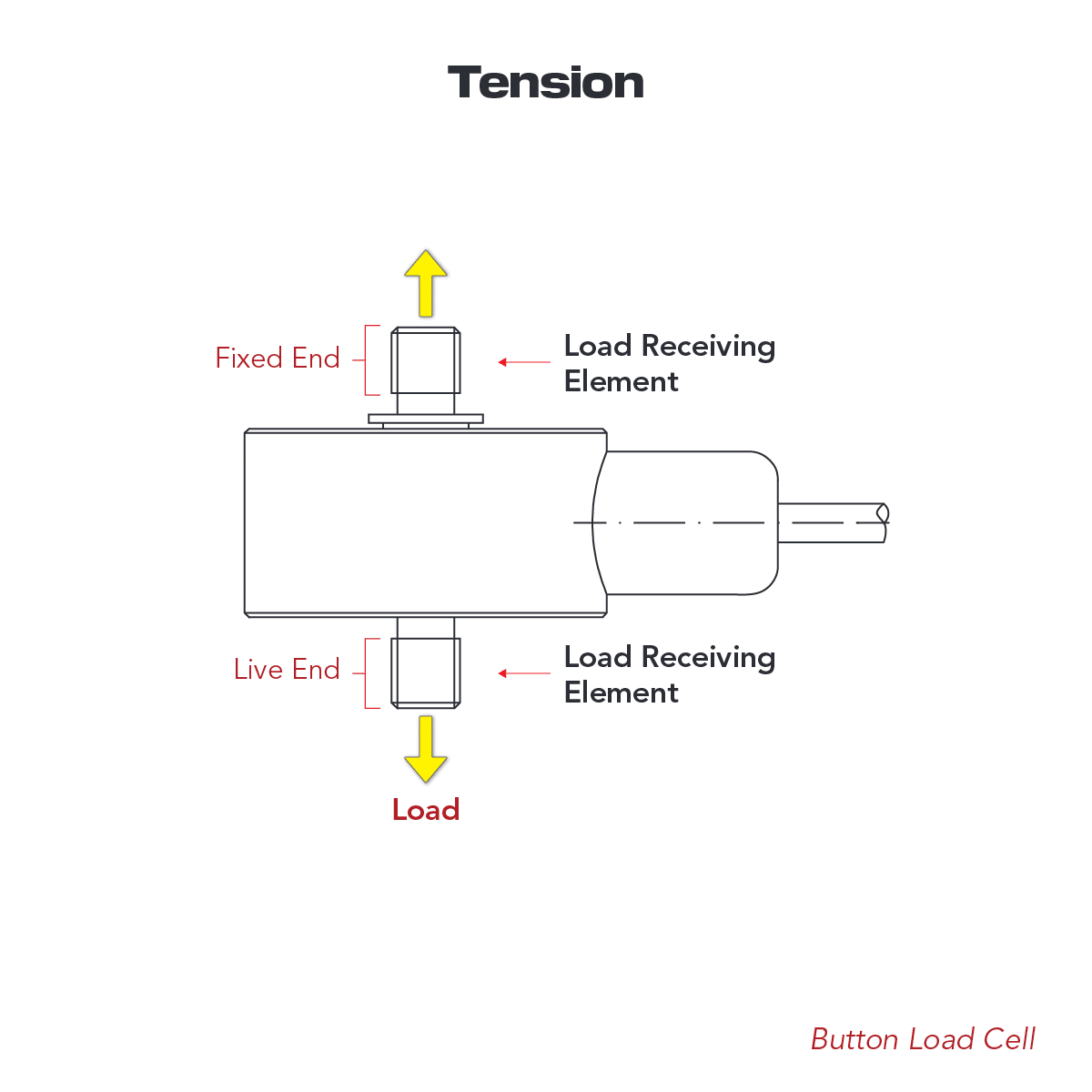
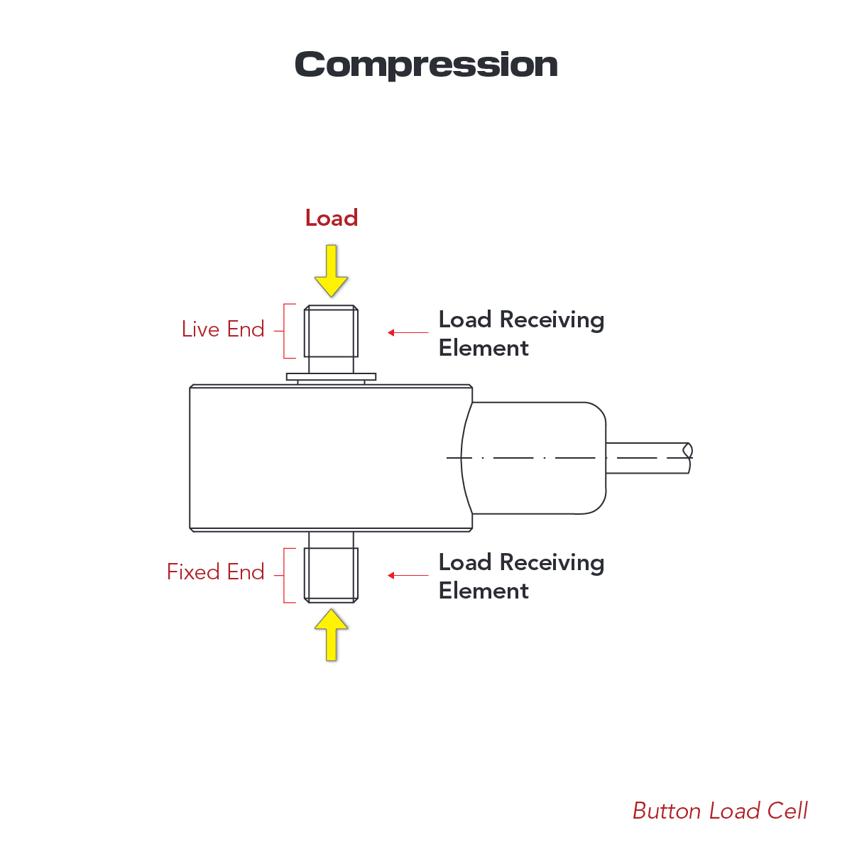
9. Button Load Cells
Button load cells (also known as “load buttons”) are designed for both tension (Fig 9.1) and compression (Fig 9.2), especially where space and or weight are limited. By design, it is like the disc load cells, providing a compact solution where very high precision is not the primary objective. Common applications include robotics, professional sports equipment, medical equipment, and consumer electronics. For best performance and longer service life, the load should be applied without the presence of any side load or torque influence.
10. Disc Load Cells
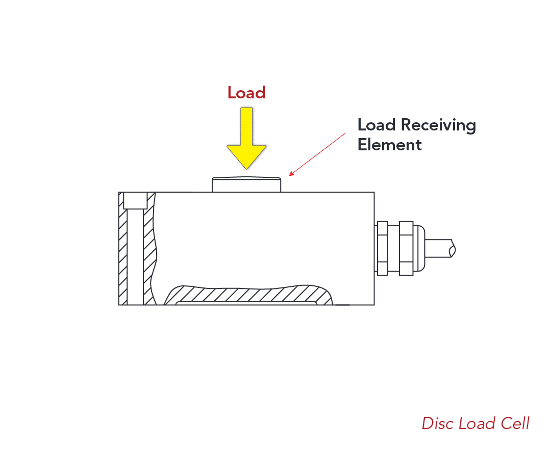
Disc load cells offer a low profile, higher capacity solution while compensating well against side force (100% of capacity). Slightly lower cost, relatively lower accuracy, as compared to canister load cells, the core design is fundamentally similar to canister load cells. High-precision disc load cells offered by a select few manufacturers in the industry are commonly found in precision test machines utilizing hydraulic and/or screw-type machines in force measurement. In these cases, these certified disc load cells are used as a “secondary standard” to control the applied force of the machine and used to calibrate new load cells.
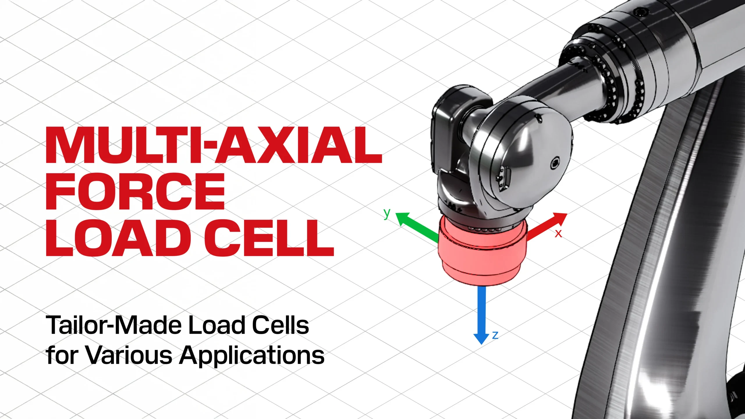
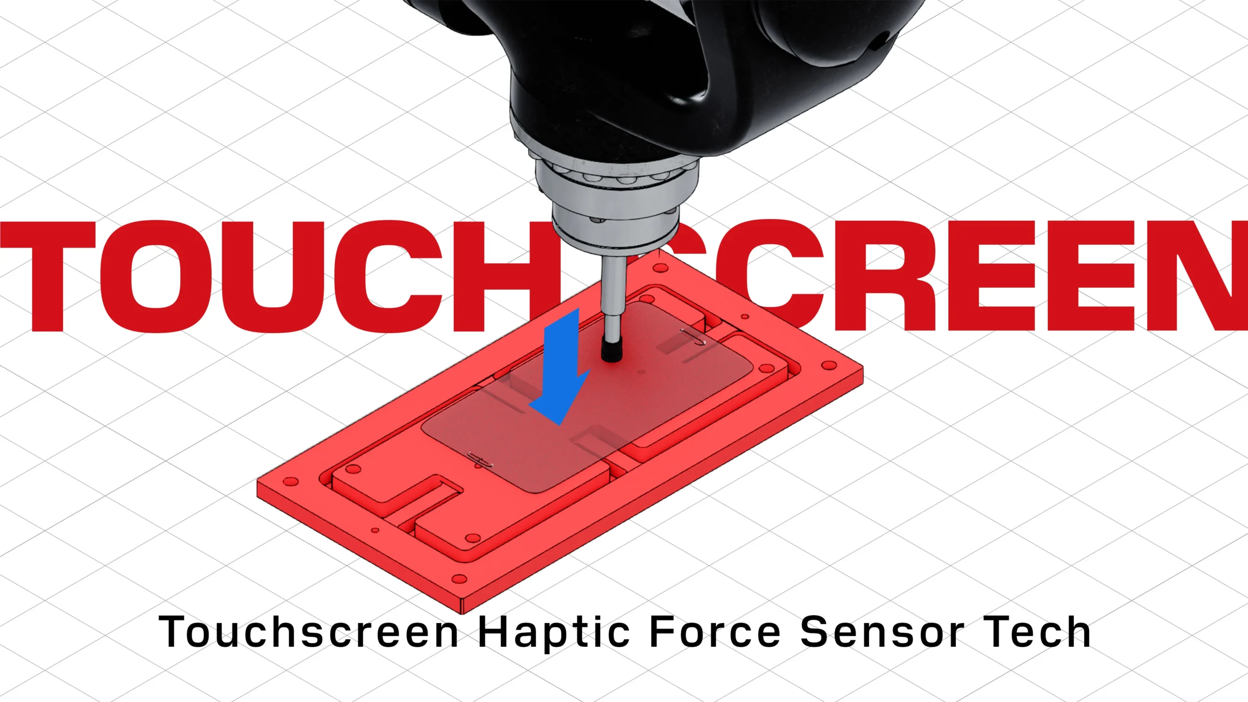
11. Multi-Axial Load Cells
Unlike other load cell design categories, multi-axial load cells are defined by their functional capability rather than its form. Multi-axial load cells can take a variety of shapes but are all designed to measure force or loads along multiple axis. For example, a miniaturized multi-axial load cell might be designed specifically to fit in-line with a robotic arm to ensure safety and provide haptic feedback to the operator, and this single sensor could measure compression along the Y axis and tension along the Z axis. These load cells are generally not available as standard products and can take many interesting shapes and sizes depending on applicational requirements.