


DESIGN – Guide to Vessel Weighing
Last Updated On • 15 min read
Designing a vessel weighing system requires careful consideration of mechanical structure, load cell selection, environmental influences, and process integration. Unlike standalone platform scales, vessel weighing systems must be designed to accommodate real-world conditions such as material flow dynamics, structural expansion, vibration, and process-related forces. A well-designed system ensures accurate, repeatable measurements while minimizing maintenance and operational disruptions.
The type of vessel being weighed plays a crucial role in system design. Factors such as support structure (legs, skirt, frame, or suspended), material flow characteristics, and operational environment will determine the optimal load cell configuration and mounting method. Additionally, achieving the desired accuracy level requires balancing sensor selection, external force isolation, and calibration strategies.
This section explores the technical aspects of vessel weighing system design, covering the engineering principles and best practices necessary for an effective and reliable implementation.
Types of Weighing Vessels
Vessel weighing systems are essential across industries for monitoring and controlling stored, processed, or dispensed materials. While terms like tanks, silos, and hoppers are often used interchangeably, their definitions vary by industry, region, and application. A grain silo in agriculture functions similarly to a powder storage hopper in a chemical plant, just as a mixing vessel in pharmaceuticals may be called a reactor in petrochemical industries.
Despite differences in name, shape, size, and function, these vessels share common weighing challenges such as vibration, side loading, environmental exposure, and structural constraints. At the same time, each vessel type presents unique operational and mechanical considerations, requiring tailored solutions for load cell selection, mounting, and accuracy optimization. The following section provides a detailed breakdown of major vessel types, their key characteristics, and specific weighing challenges.
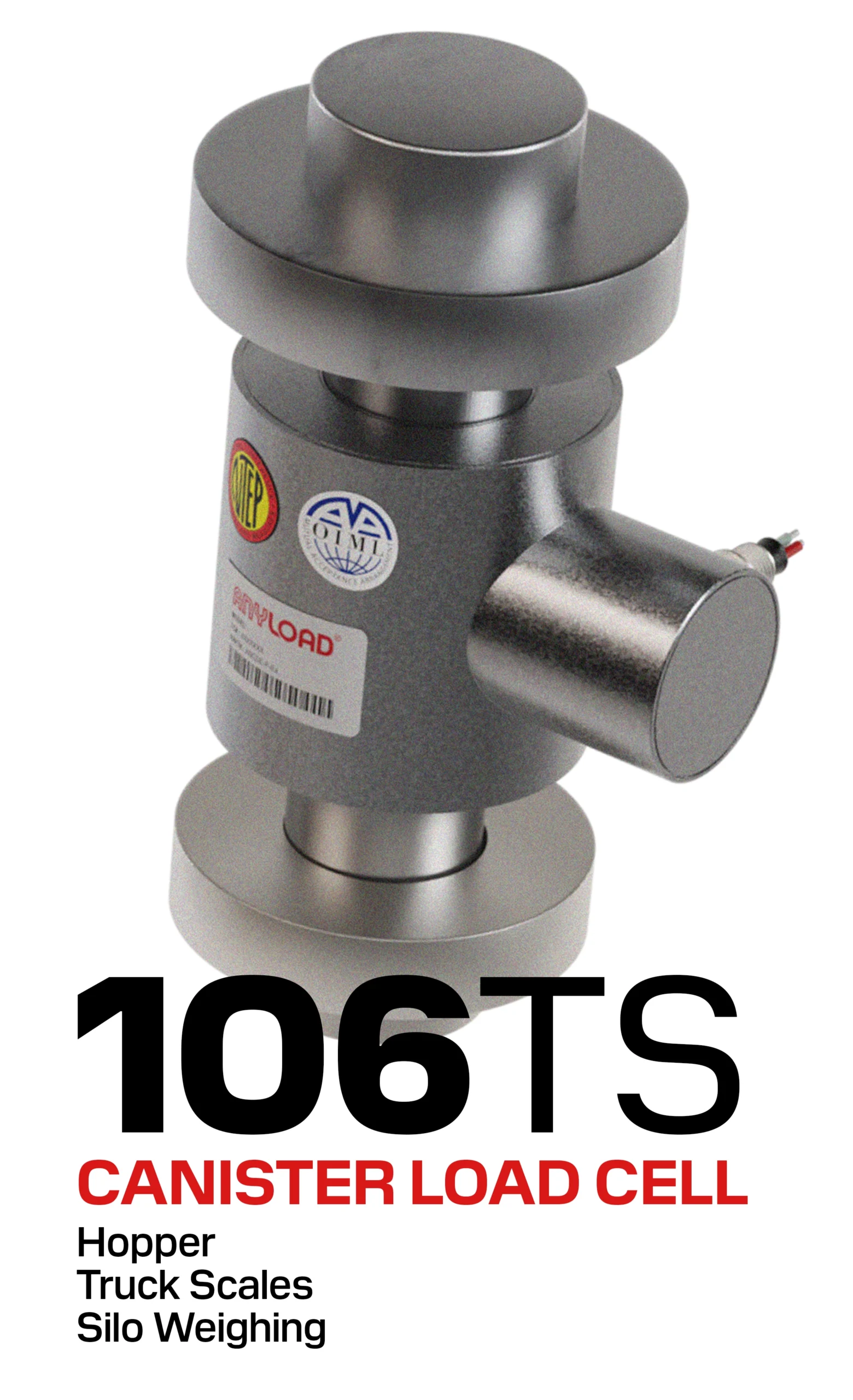
1. Hoppers
Hoppers are generally open-top and funnel-shaped containers designed for handling powdered, granular, or free-flowing materials such as cement, flour, plastic pellets, and chemical powders. These vessels are commonly found in manufacturing, food processing, and bulk material handling industries, where materials are dispensed in controlled batches or collected from an upstream process. Hoppers may be suspended from a frame or supported on legs, depending on the application.
Key Weighing Considerations for Hoppers:
- Suspended vs. Supported Configuration – Suspended hoppers (using tension load cells) are ideal for batching systems, while supported hoppers (using compression load cells) provide better structural stability.
- Material Flow & Accuracy: Irregular or uneven material discharge can lead to fluctuations in weight readings. Proper design and load cell placement help minimize these errors.
- Impact Loads: When materials are dumped into a hopper, they can create sudden forces on the load cells, which may require shock-absorbing mounts or damping mechanisms.
- Dust & Environmental Factors: Fine powders can clog mechanical components or contaminate load cell connections, requiring sealed weighing systems for durability.
Standard Mounting Configurations:
2. Tank
Tanks are generally enclosed containers used to store or process liquids, gases, and free-flowing solids. They range in size from small propane tanks to extremely large industrial storage tanks used in chemical processing, water treatment, and oil & gas industries. Tank weighing systems provide continuous level monitoring and precise material measurement without the need for external sensors like ultrasonic or radar level indicators.
Key Weighing Considerations for Tanks:
- Fluid Movement: Liquid tanks may experience sloshing effects, which can cause weight fluctuations; filters and strategic load cell placement help mitigate these effects.
- Thermal Expansion: Tanks exposed to temperature changes temperatures may expand or contract, introducing measurement drift.
- Structural Rigidity: Large tanks with fixed support structures may introduce mechanical constraints that interfere with accurate weighing. Flexible mounting solutions help minimize these issues.
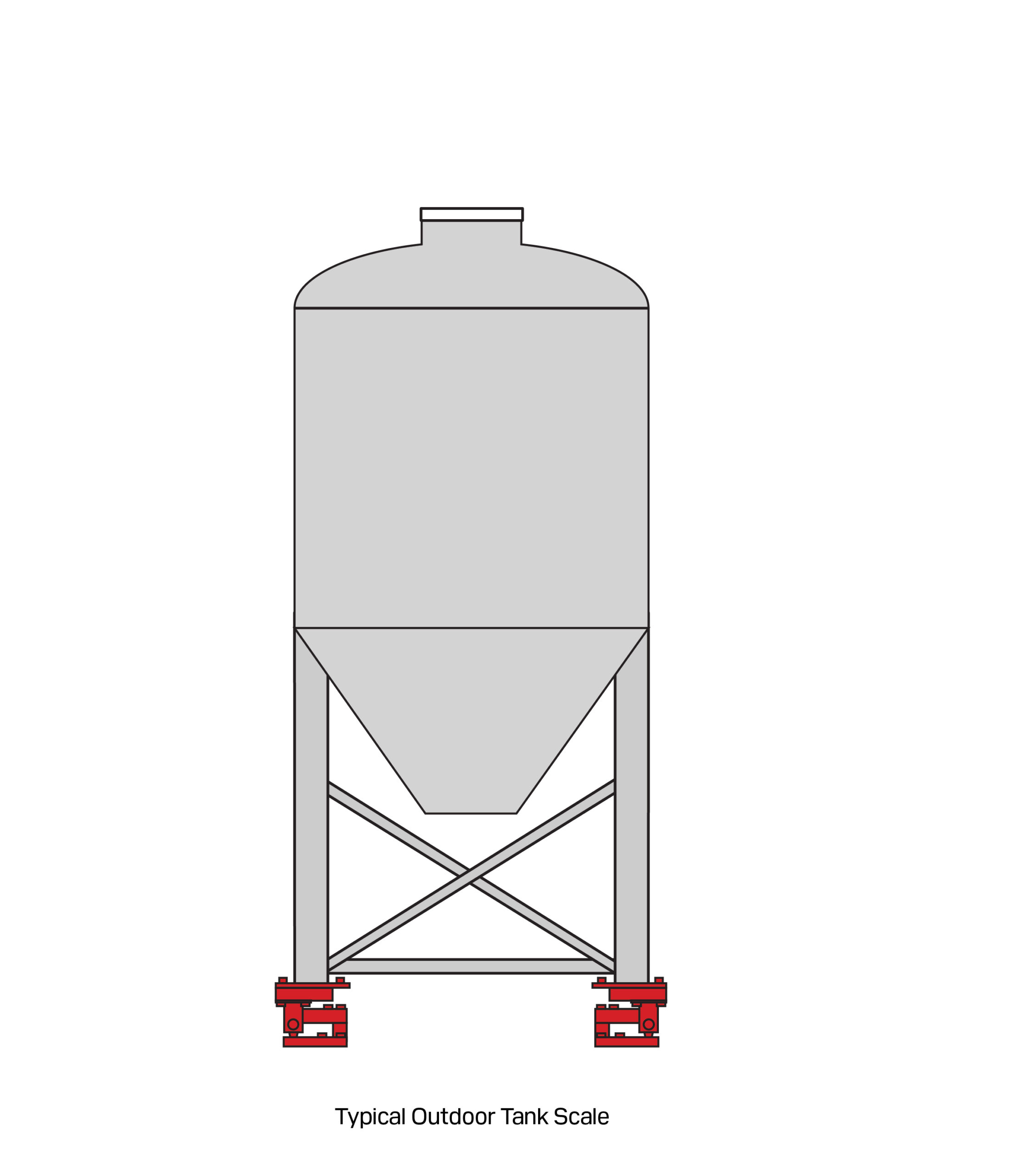
3. Silos
Silos are generally large vertical storage structures designed for bulk materials such as grains, cement, coal, and industrial chemicals. Unlike hoppers, which are integrated into a processing system, silos are primarily used for long-term storage and require specialized weighing solutions due to their height, mass, and environmental exposure.
Key Weighing Considerations for Silos:
- Wind & Environmental Forces: Outdoor silos are exposed to wind, thermal expansion, and seismic forces, which can shift load distribution, affecting weight readings and require safety considerations.
- Structural Movement: Due to their height, weight, and being mounted on multiple legs, silos may experience slight flexing or settling over time. Using self-aligning load cells and mounts improves accuracy.
- Load Distribution: Material may accumulate unevenly, causing off-center loading that requires multipoint weighing systems.
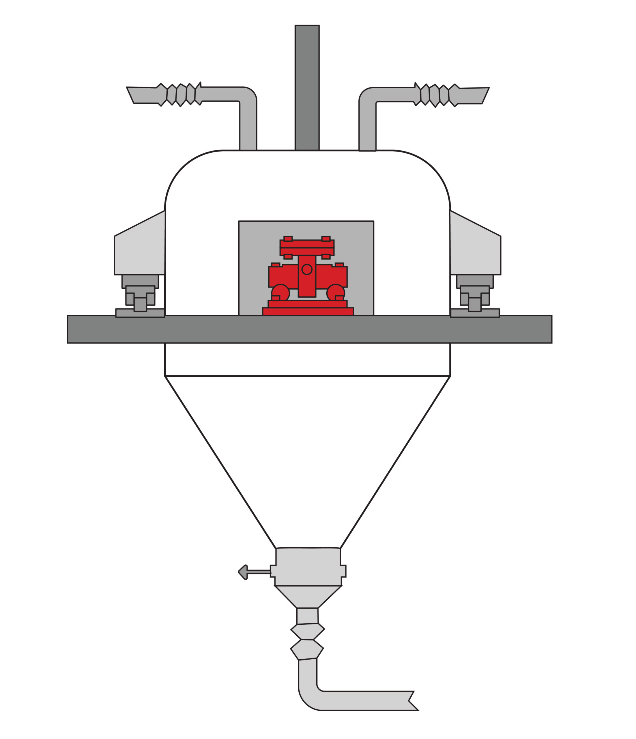
4. Process Vessels & Reactors
Process vessels and reactors are generally specialized tanks with mixing, heating, cooling, or chemical reaction capabilities. Common in pharmaceuticals, chemical manufacturing, and food production, these vessels require high-precision weighing to ensure batch consistency and process control.
Key Weighing Considerations for Process Vessels & Reactors:
- Agitation & Mixing Forces: Rotating blades and agitators introduce vibration that can affect weight accuracy and in serious cases can introduce fatigue to the load cell.
- Piping & Mechanical Connections: Rigid piping can transmit forces to load cells, requiring flexible pipe connections.
- High-Precision Requirements: When accuracy is critical due to high-value materials, regulatory compliance, or process control demands, careful system design is essential to ensure the weighing system meets performance targets.
- Vacuum & Pressure Fluctuations: Changes in internal pressure can alter apparent vessel weight by causing slight expansion or contraction of the structure, changing the way forces are distributed to the load cells.
While tanks, hoppers, silos, and process vessels each present unique challenges, the fundamental principles of vessel weighing remain the same. Regardless of the vessel type, accurate and reliable measurements depend on proper load cell selection, strategic mounting, and effective isolation from external forces. Issues such as vibration, structural movement, and mechanical interference can distort weight readings, but these challenges are mitigated using common engineering solutions.
With a clear understanding of vessel types, the next step in system design is establishing basic performance requirements, ensuring the system is suited to its intended application.
NOTE: General Vessel Design Tips for Optimal Weighing
Minimize support points – Three-point support self-levels and simplifies calibration, while four-point provides stability against tipping. More than four legs complicate load distribution.
Allow clearance for installation & maintenance – Provide sufficient space around load cells, calibration, and servicing, especially in indoor or confined areas.
Ceiling clearance – In indoor facilities, consider whether the vessel will require lifting for installation or service and ensure adequate overhead clearance.
Balance rigidity & flexibility – Avoid excessive structural stiffness, which can cause thermal expansion stress or load-shifting forces. Use self-aligning mounts to compensate for minor misalignments.
Accuracy
Achieving precise and repeatable weight measurements starts with defining accuracy requirements, which are dictated by the application’s needs. Whether a vessel weighing system is used for legal-for-trade transactions, general process control, or simple level monitoring, the required accuracy level influences load cell selection, system configuration, and overall design.
Accuracy Classification:
The accuracy requirements for hopper, tank, and silo weighing generally fall into three basic categories:
| Accuracy Level | Tolerance Range | Typical Application |
|---|---|---|
| High Accuracy | ±0.02% ~ ±0.10% | Legal for trade scales |
| Medium Accuracy | ±0.10% ~ ±0.50% | General-purpose weighing |
| Low Accuracy | ±0.50% ~ 5.00% | Level detection |
Weighing accuracy depends on both system design and external influences. For static weighing applications, the highest achievable system accuracy is typically 5,000 divisions—for example, a 50-ton system would have a 10kg division.
For process weighing applications, accuracy is more challenging to quantify, often leading to vague requirements like “as accurate as possible.” However, real-world accuracy can be estimated by summing the individual errors from external influences. In complex process weighing, external factors usually limit maximum achievable system accuracy to 750 divisions, making early design-stage evaluation critical.
Safety Considerations in Design:
Ensuring structural and operational safety is a critical aspect of vessel weighing system design. Load cell systems must not only provide accurate weight measurements but also support the vessel’s full load capacity under normal and extreme conditions. However, safety considerations—especially safety factors in load cell selection and system design—can have a direct impact on weighing accuracy. Striking the right balance between safety and measurement precision is key to an effective and reliable system.
Safety Factor
Safety factor refers to the additional load capacity designed into a system beyond its expected maximum operational load. This ensures that the system can withstand unexpected forces, such as shock loads, overloading, or environmental influences like wind and seismic activity.
Typical safety factors for load cells:
- Static weighing systems (e.g., silos, storage tanks): 1.5x to 2.0x expected load
- Dynamic weighing systems (e.g., process vessels, batching hoppers): 2.0x to 3.0x expected load
- High-risk environments (e.g., high-impact applications): 3.0x+ expected load
Inverse Relationship Between Safety Factor & Accuracy
While higher safety factors provide additional load-bearing capacity, they can reduce system accuracy due to the increased load cell capacity relative to actual operating loads:
- Lower safety factors (closer to operational loads) → Higher accuracy but less tolerance for unexpected overloads.
- Higher safety factors (oversized load cells) → Lower accuracy due to decreased sensitivity in lower weight ranges.
For example, if a 50-ton tank is weighed using load cells rated for 200 tons (4x safety factor), small weight fluctuations may be less detectable due to the lower sensitivity of the load cells at typical operating weights. Conversely, selecting load cells too close to the vessel’s actual weight increases the risk of overloading, mechanical failure, or permanent deformation.
Some manufacturers may incorporate higher safety factors into their load cells, including elevated “safe overload” ratings of 125–200%, to enhance durability and protect against unexpected loads. While this can extend the lifespan of the weighing system and prevent failure under difficult conditions, it does not eliminate the inherent tradeoff wherein greater overload protection invariably comes at the cost of reduced sensitivity and therefore reduced accuracy.
Structural Safety & Mechanical Overload Protection
Beyond load cell selection, vessel weighing systems must be mechanically designed to prevent structural failure and unintended load shifts. Common safety measures include:
- Overload stops – Mechanical limiters prevent excessive force from damaging load cells during shock loading or overfilling.
- Side-load protection – Self-aligning load cell mounts and restraining hardware prevent excessive lateral forces.
- Uplift protection – Securing vessels against accidental upward forces caused by pressure buildup or rapid discharge.
Environmental & Operational Safety Considerations
External factors also play a role in safety system design:
- Seismic loading – Load cells must be rated for seismic activity in regions prone to earthquakes.
- Wind forces – Outdoor silos and tall tanks require wind bracing to avoid excess force transfer to load cells.
- Explosion-proof design – In hazardous environments, intrinsically safe load cells and FM/ATEX-certified weighing electronics are required.
Safety Considerations in Design:
Mechanical Operation Fundamentals
Load cells measure force in either compression or tension, with the voice depending on vessel design, process flow, structural constraints, and installation requirements.
Compression – The vessel is supported by load cells positioned underneath, transferring weight downward. This is the most common method, especially for fixed tanks, hoppers, and silos, as it requires only a stable concrete foundation or structural frame.
Tension – The vessel is suspended from load cells, typically using S-type load cells to measure the pulling force exerted by the vessel’s weight. This method is ideal for suspended hoppers or vessels with overhead support structures but is generally more complex due to larger mounting requirements.
Load Cell Mechanical Considerations
A common misconception is that a load cell acts as a rigid support. The main operating principle of load cells requires it to deflect precisely under highly repeatable conditions when a load is applied or removed. More importantly, if a system contains multiple load cells, the output of each load cell should remain equal for all equal loads.
Key mechanical factors include:
- Rigid Foundation – A stable foundation minimizes measurement errors caused by shifting, settling, or uneven terrain.
- Avoiding Force Shunts – Mechanical connections such as rigid piping, bracing, and wiring should be flexible to prevent unintended force transfer.
- Load Distribution – Ensure even weight distribution across all load cells to prevent uneven or overloading individual units.
- Floating vs. Fixed Supports – Multi-load cell systems should include a combination of floating and fixed supports to accommodate expansion and contraction.
Load Cell Selection
Weigh Modules in Vessel Weighing
When designing a vessel weighing system, proper load cell selection and mounting are critical for accurate, repeatable measurements. However, a common mistake is assuming that a load cell alone is sufficient—incorrect mounting, misalignment, and unintended force paths can significantly impact performance.
This is where weigh modules come in. A weigh module is a complete assembly that includes a load cell, mounting hardware, and force isolation features, specifically designed to ensure the correct force is applied to the load cell without interference from external factors.
Weigh modules are strongly recommended for all hopper, tank, and silo applications because they:
- Ensure proper force introduction – Prevent side loading, off-axis forces, and misalignment, which can distort weight readings.
- Simplify installation & maintenance – Designed for easy alignment, reducing setup errors and long-term calibration drift.
- Enhance system stability – Many weight modules feature uplift prevention, side load protection, vibration isolation, and thermal expansion compensation, addressing common challenges in vessel weighing.
While it is possible to install bare load cells with custom mounting, inadequately designed mounting configurations can lead to inaccurate readings, mechanical strain, and even premature load cell failure. Using weigh modules eliminates these risks, ensuring accuracy and longevity.

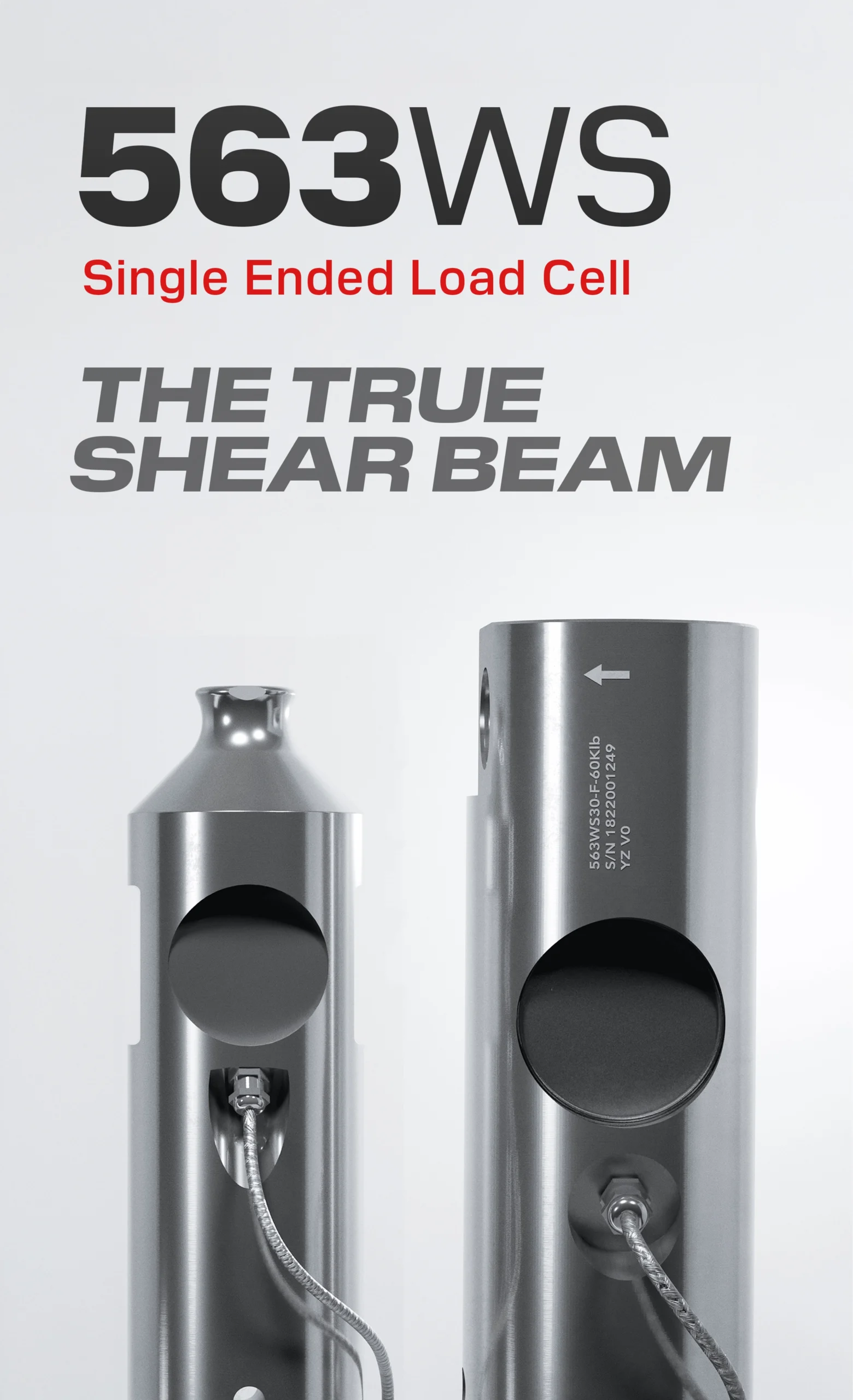
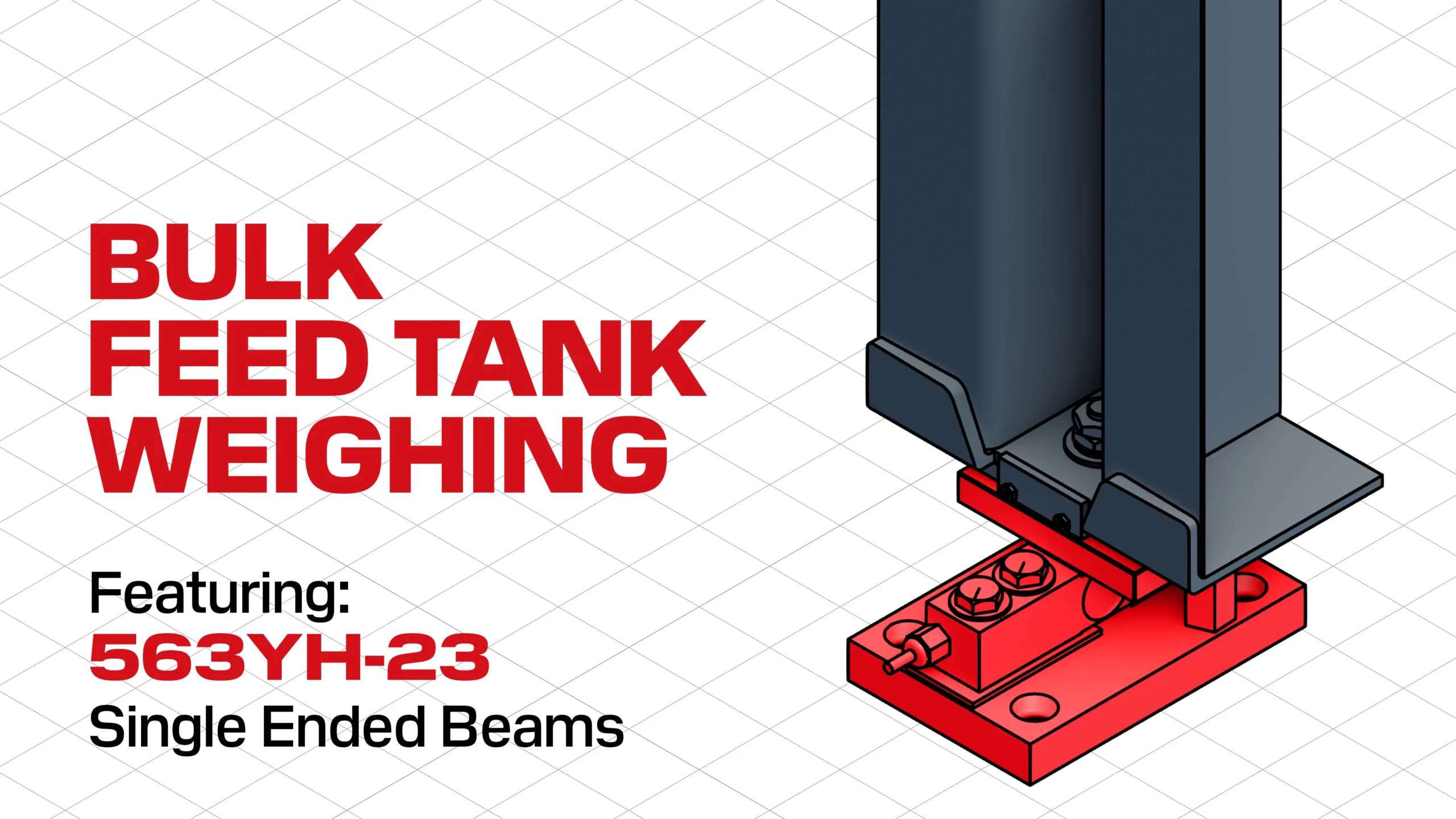
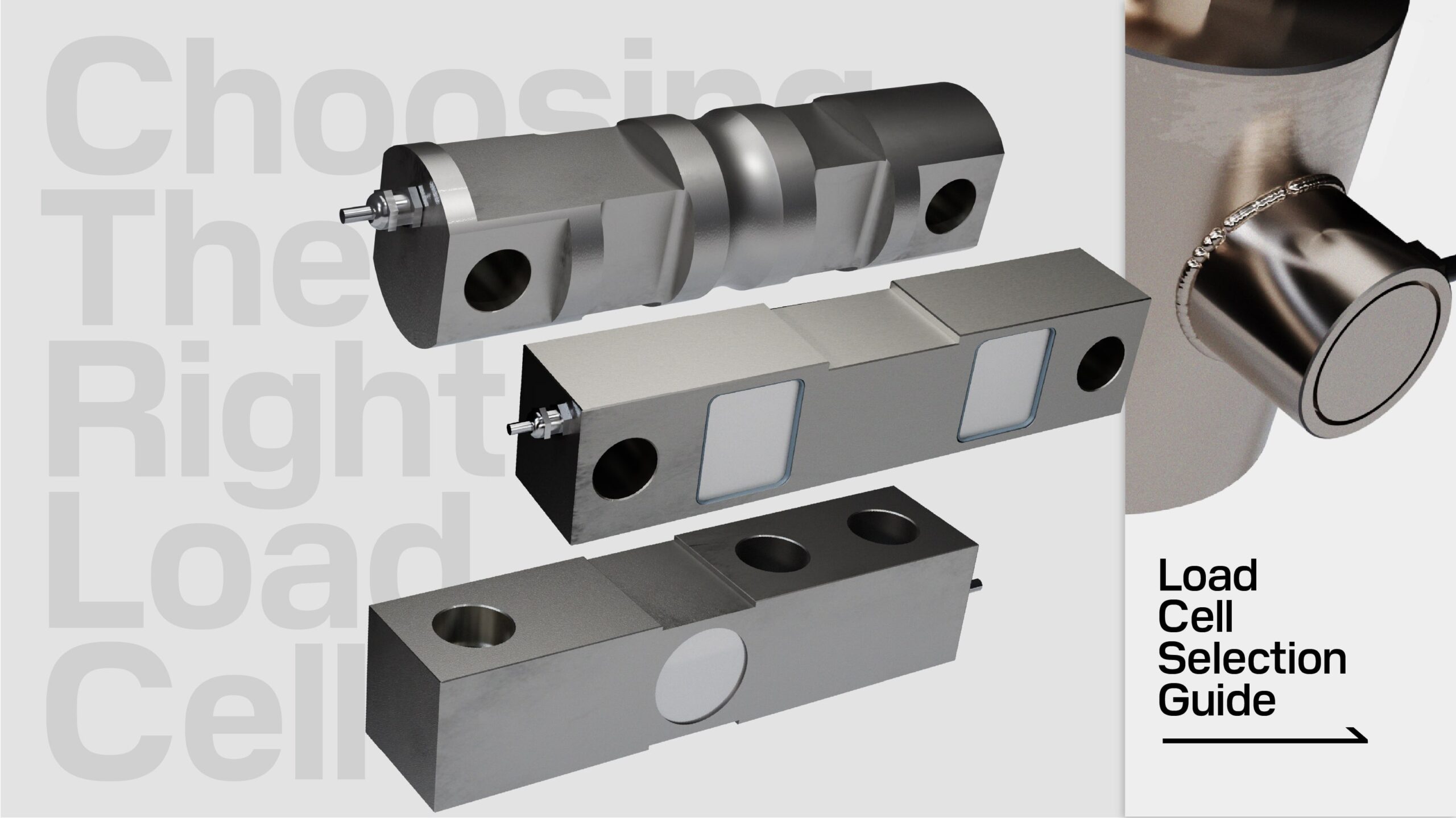
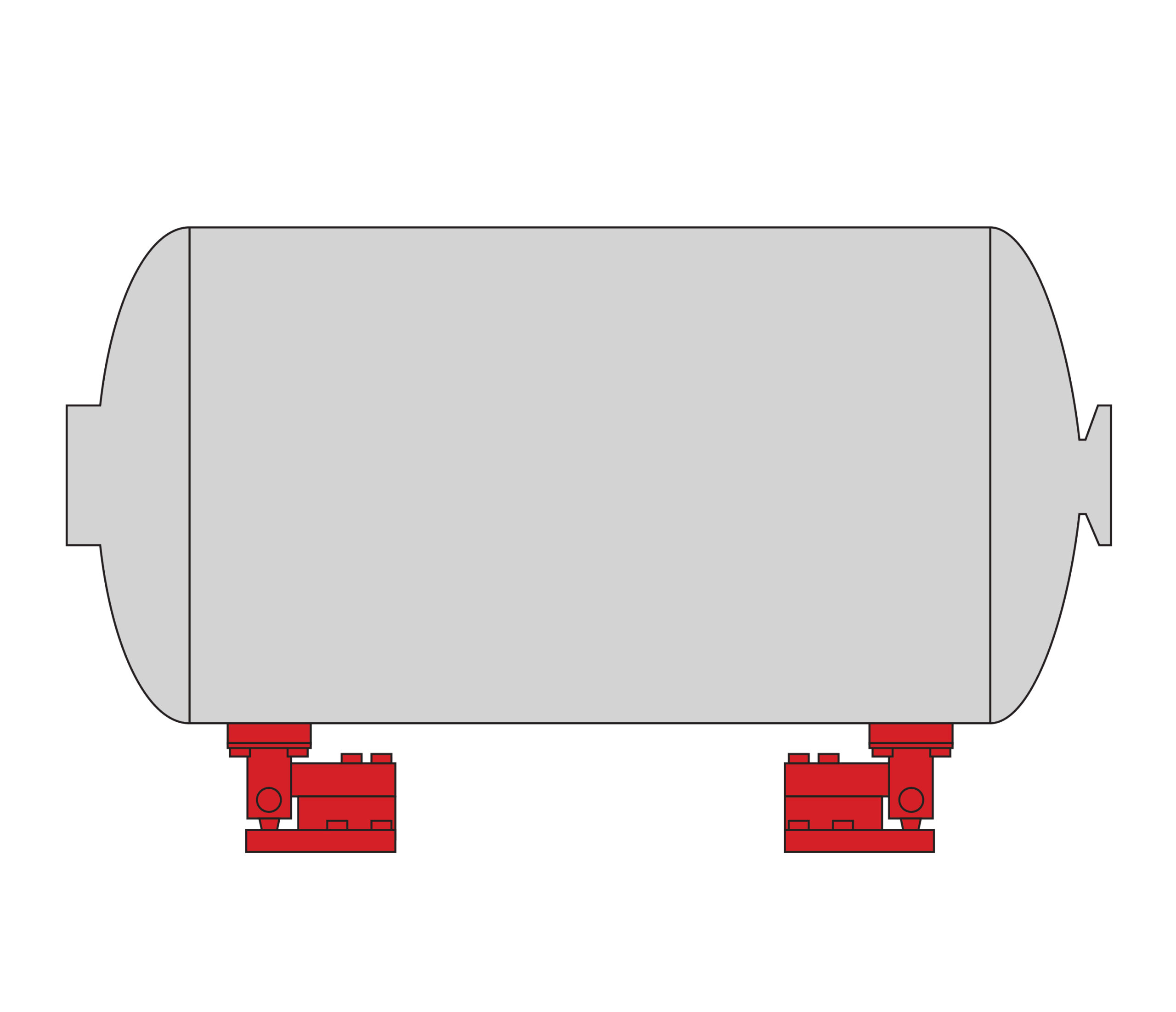
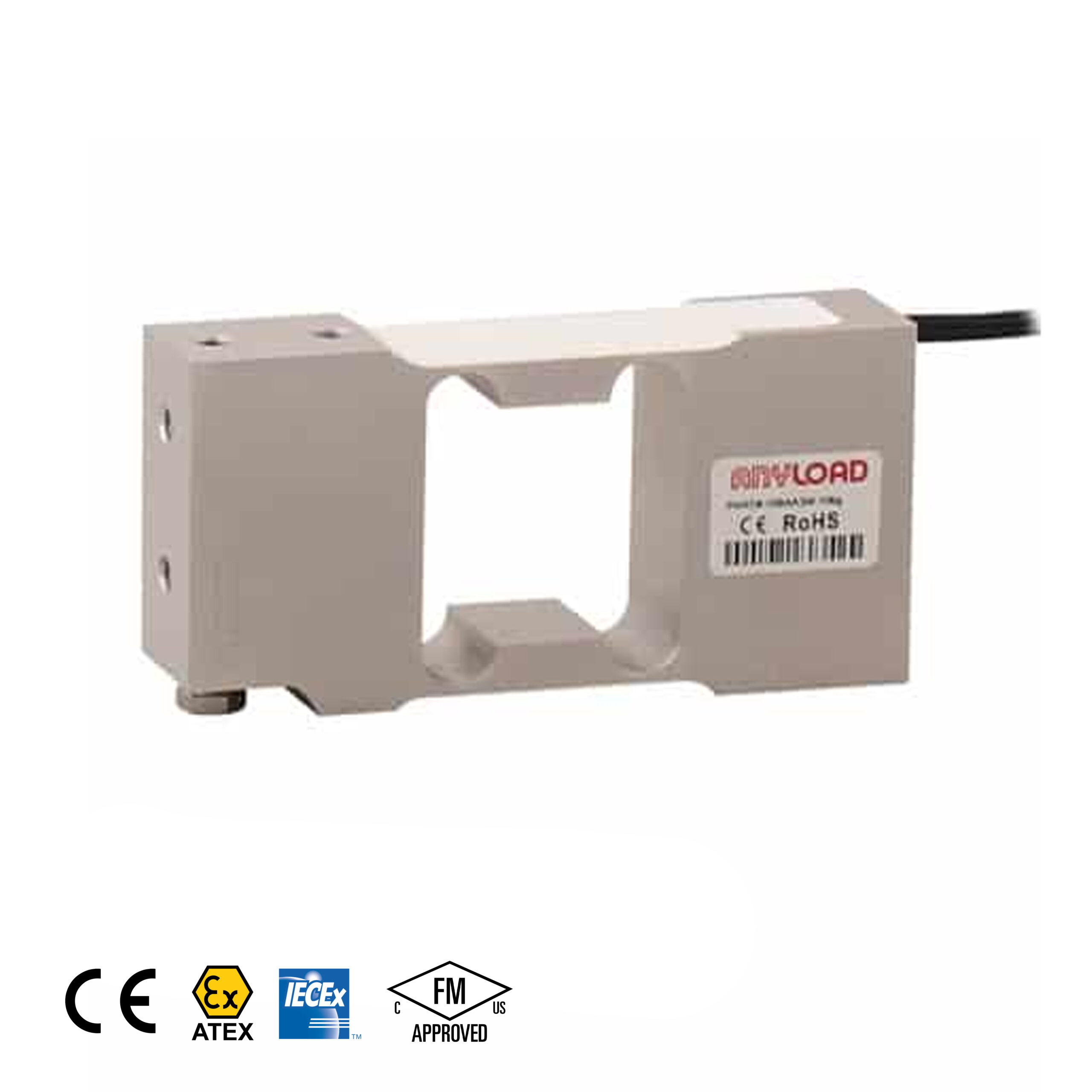
Single Ended Beam Load Cell & Module
Suitable for small to medium hoppers with moderate loads. They’re cost effective while maintaining a high accuracy. Single shear beam load cells can be attached directly to floors, piers, or structural beams with vessels mounted directly on top of them.
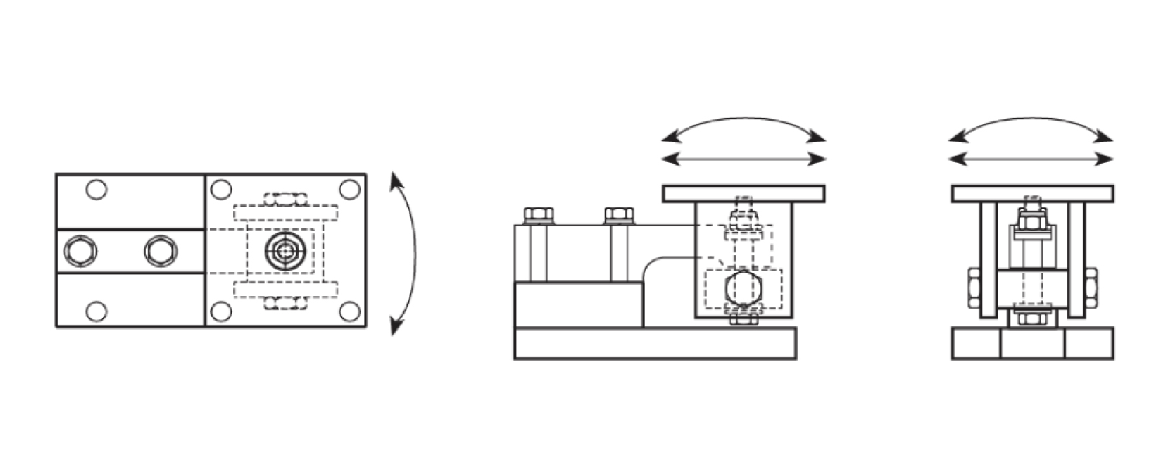
A common example of a compression weigh module is shown in Figure 1. It consists of a load cell, a top plate (that bolts to the structure overhead), a base plate (that bolts to the floor of the support surface), and anti lift bolts that resist upwards forces, such as the vessel tipping.
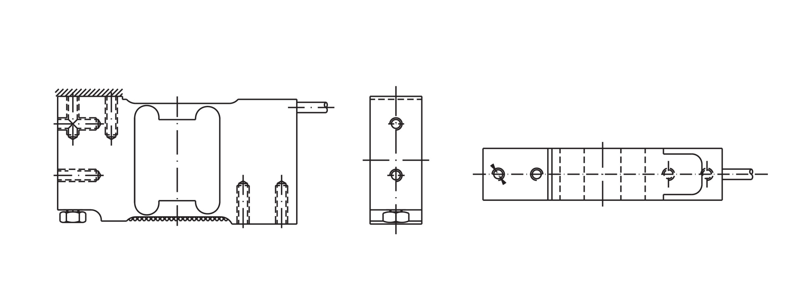
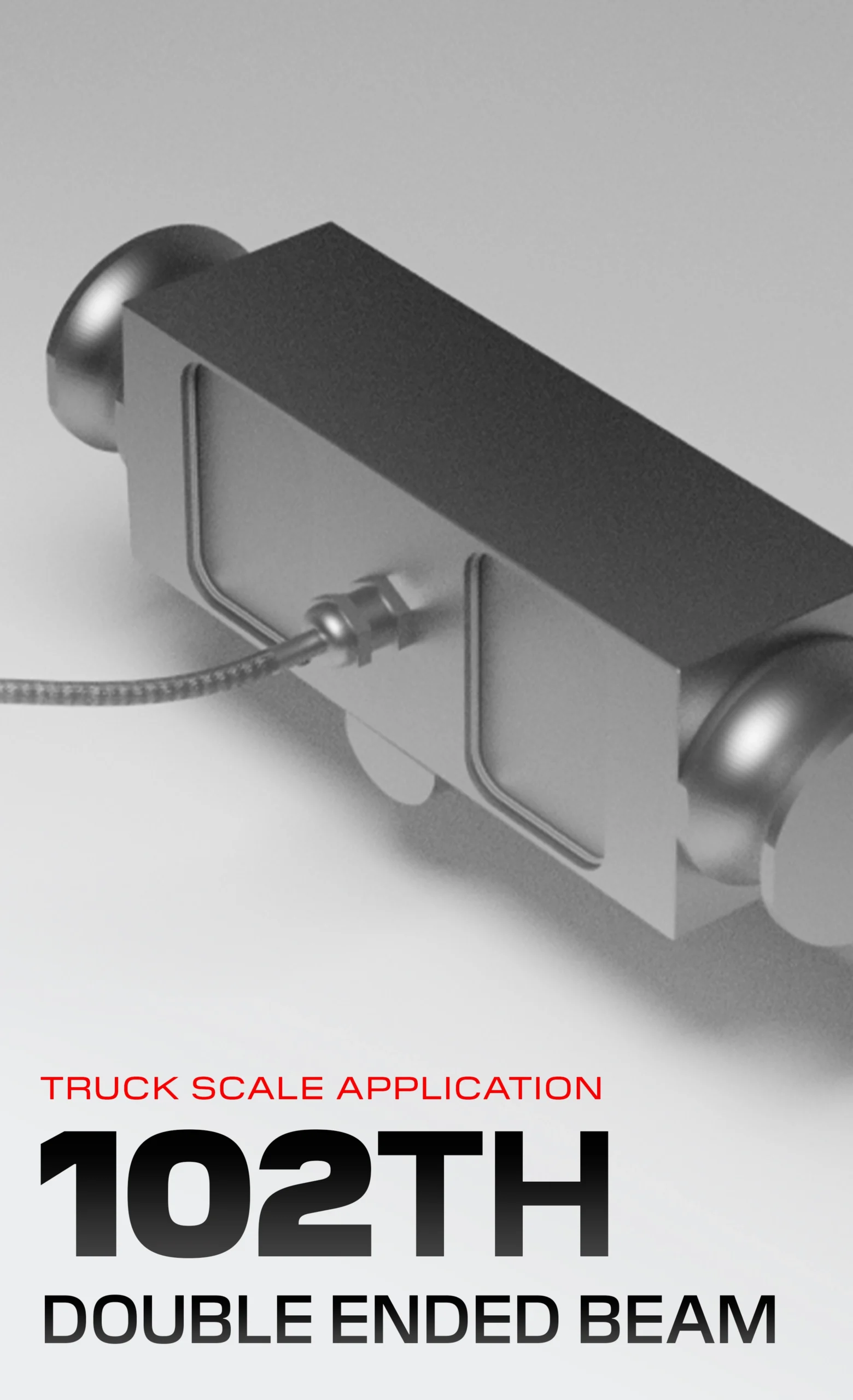
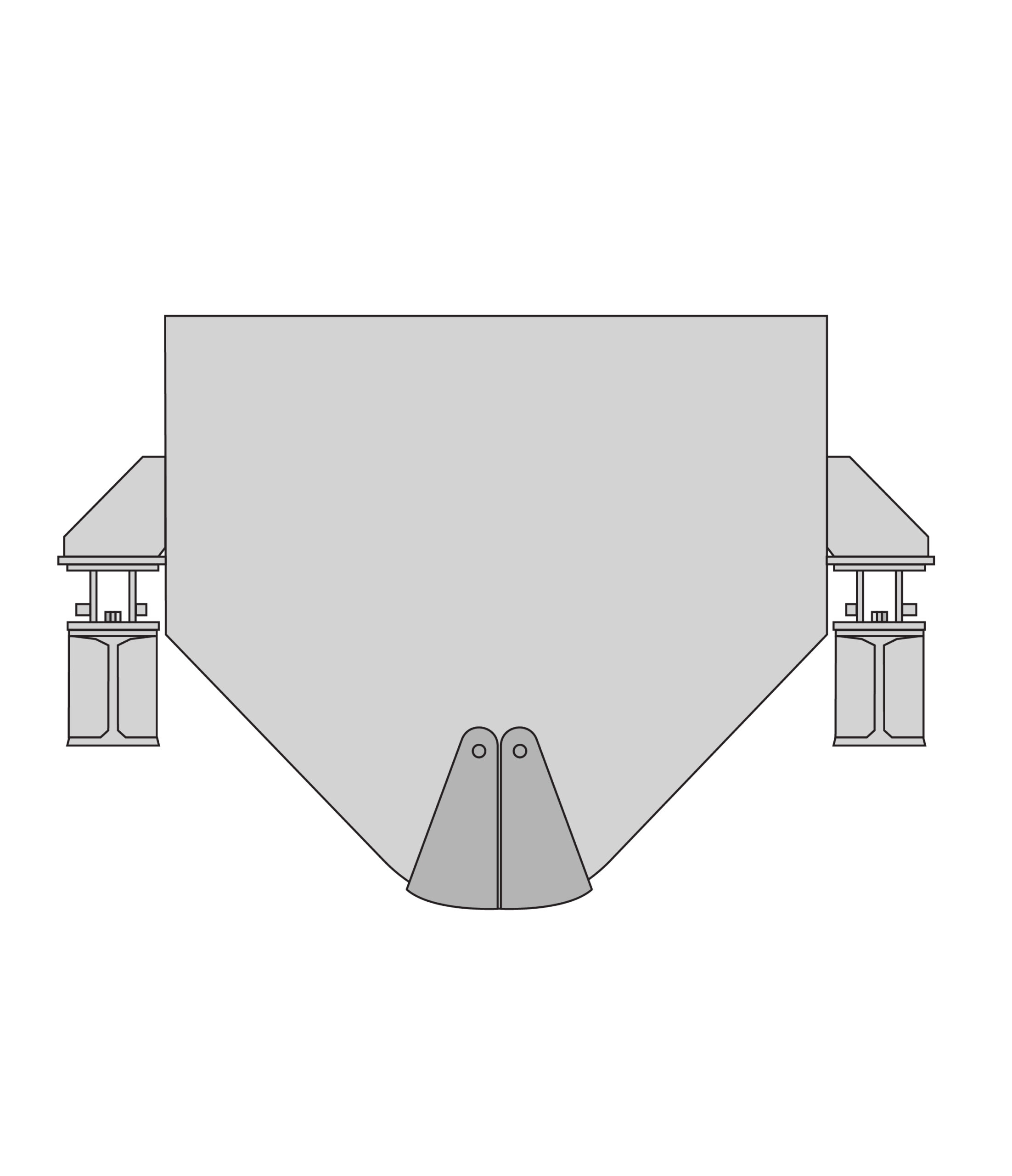
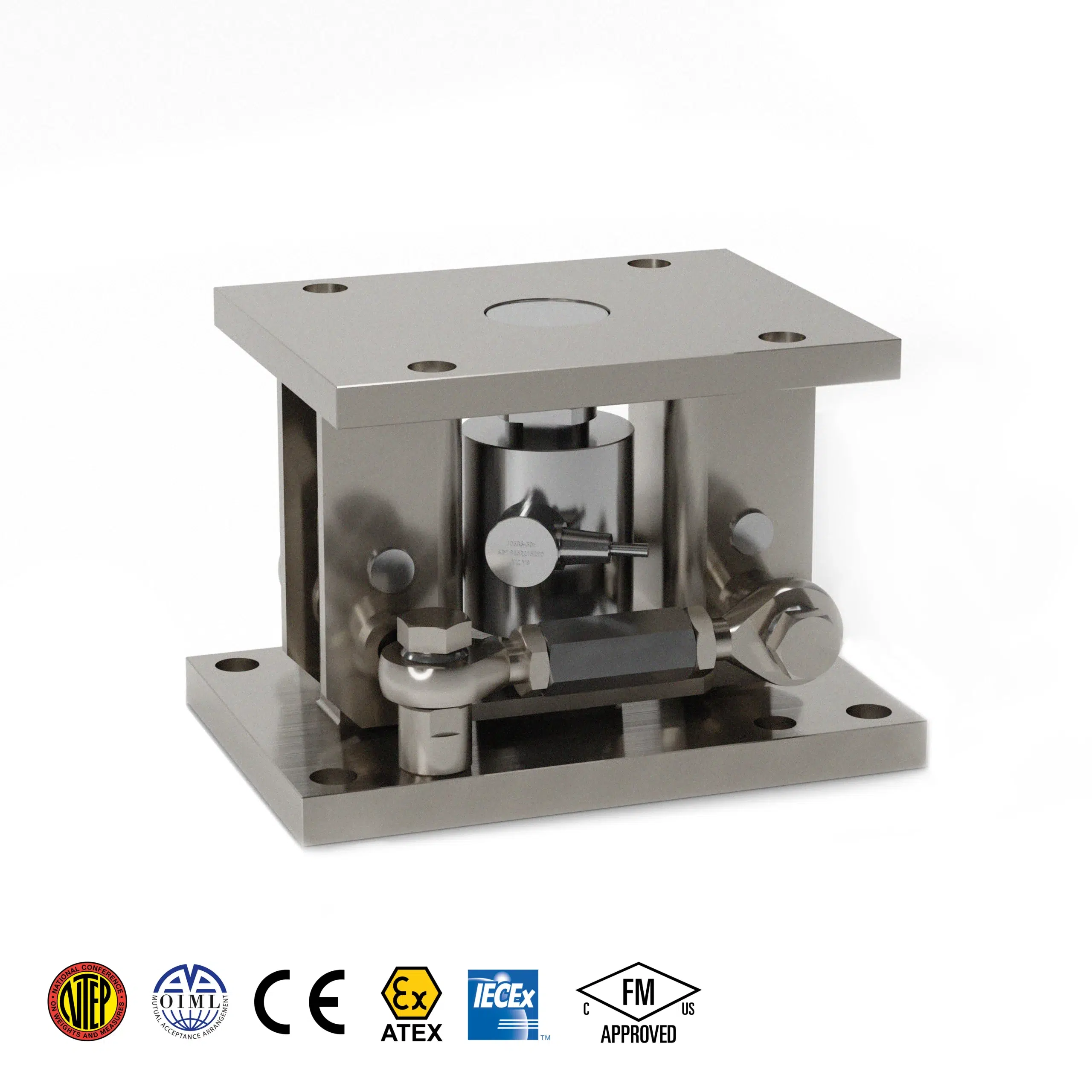
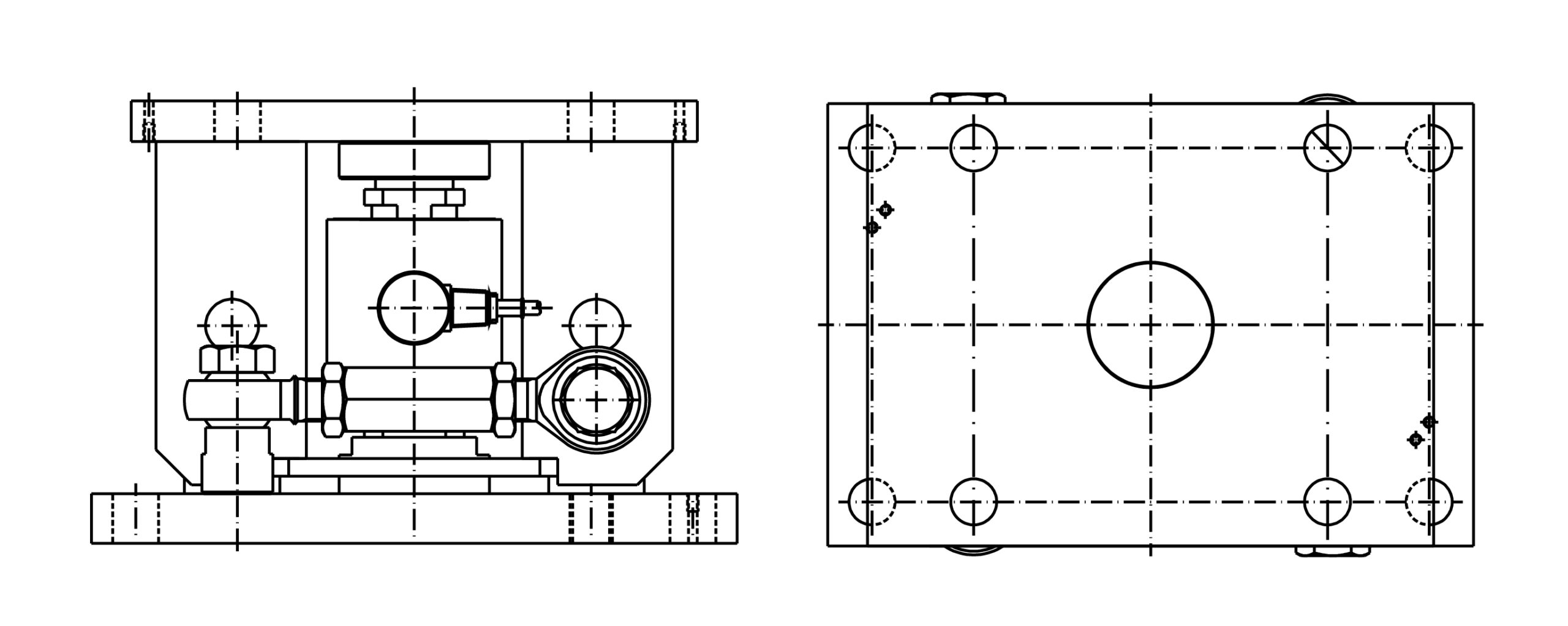
Double Ended Beam Load Cell & Module
Used for higher capacity hoppers or applications requiring enhanced stability. They offer additional side load protection compared to single shear beams, works well in windy environments with large outdoor silos installed. Like single shear beams, double shear beam load cell weigh modules can also be bolted directly to support structures, but are chosen when the hopper will be installed in more demanding environments.
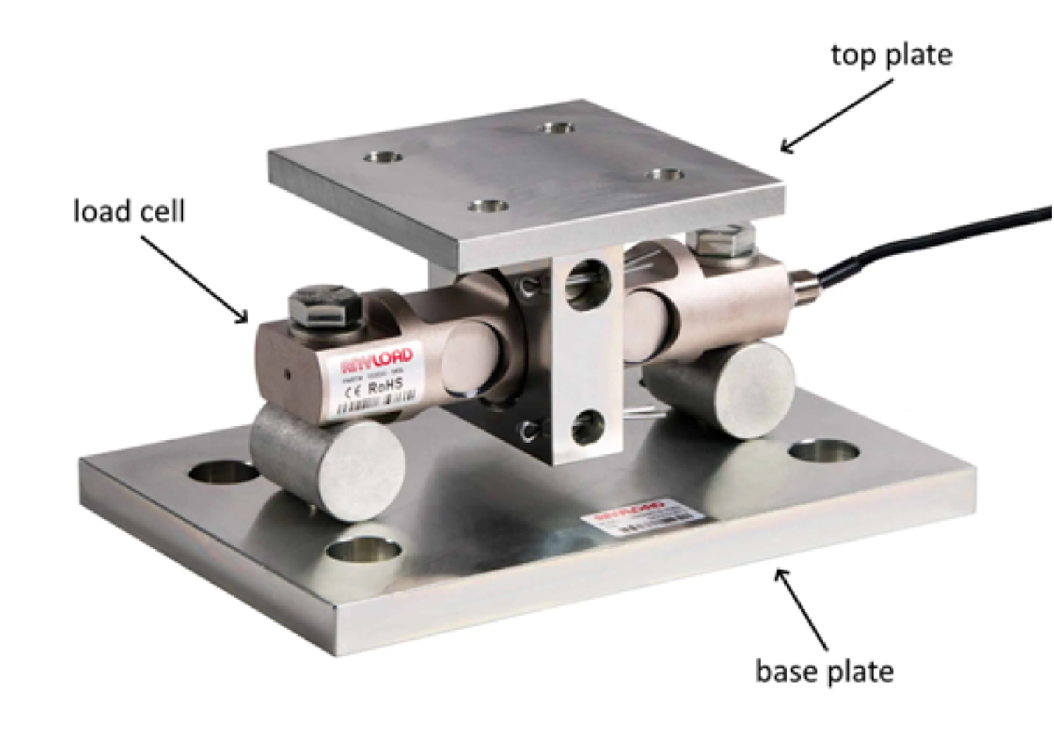
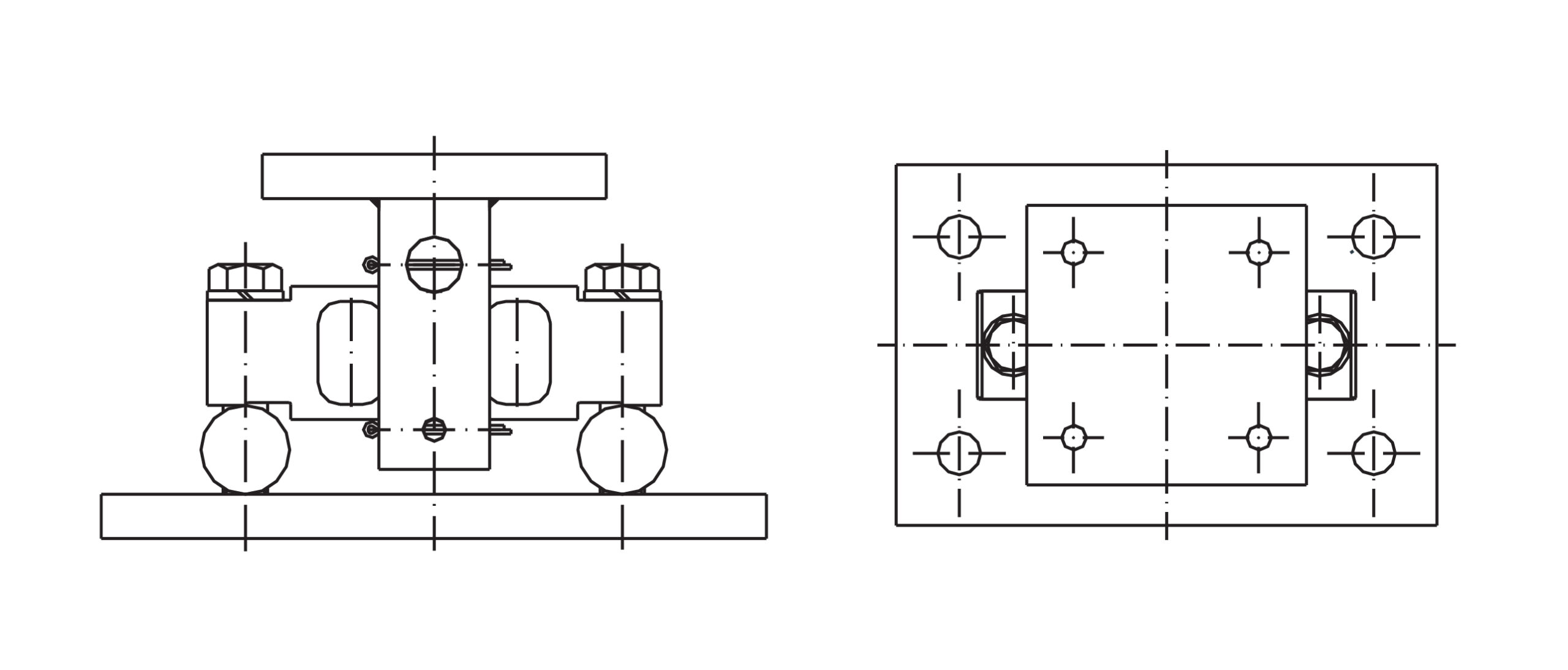
Figure 2 illustrates a common example of a double shear beam compression weigh module. The main components are comparable to a single shear beam weigh module, but it does not incorporate anti-lift bolts due to the double support design of the load cell.
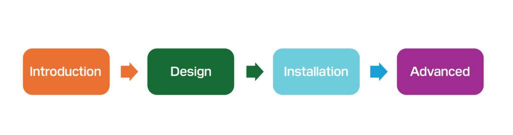
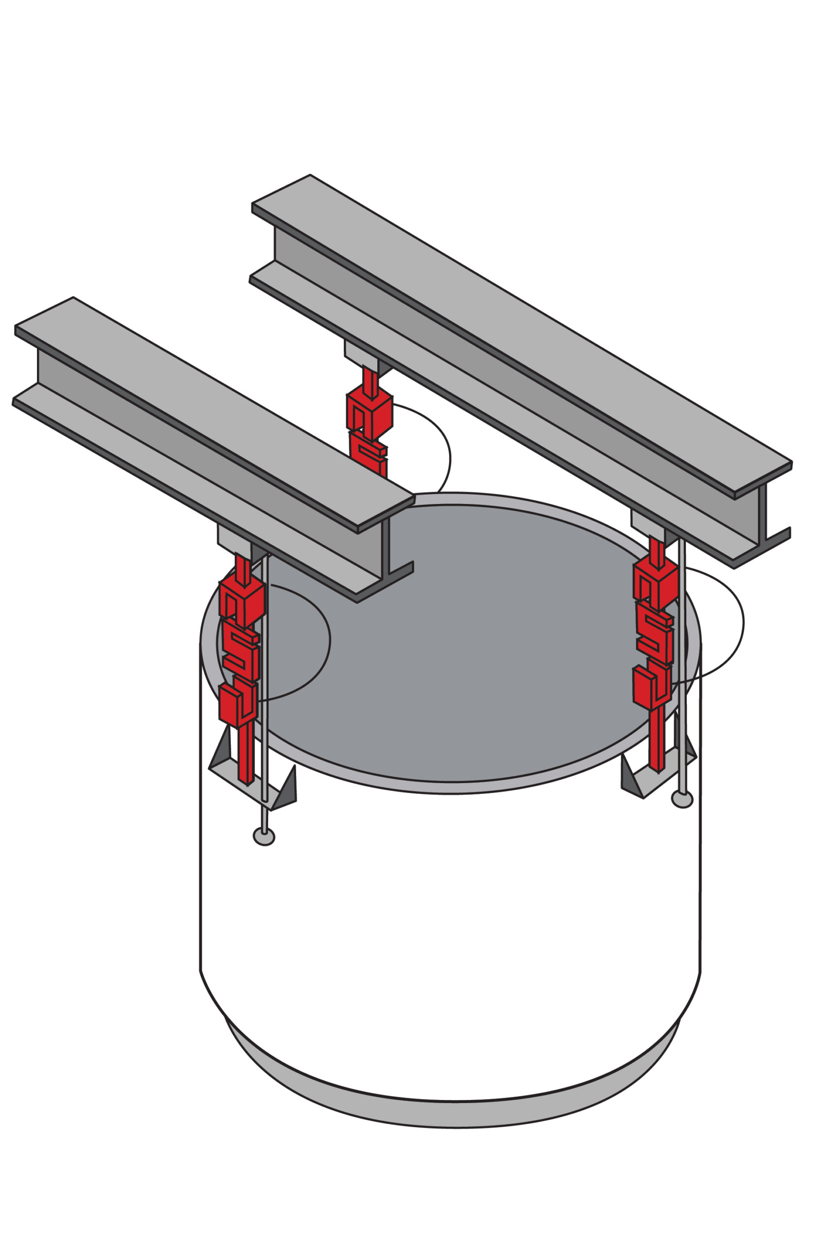
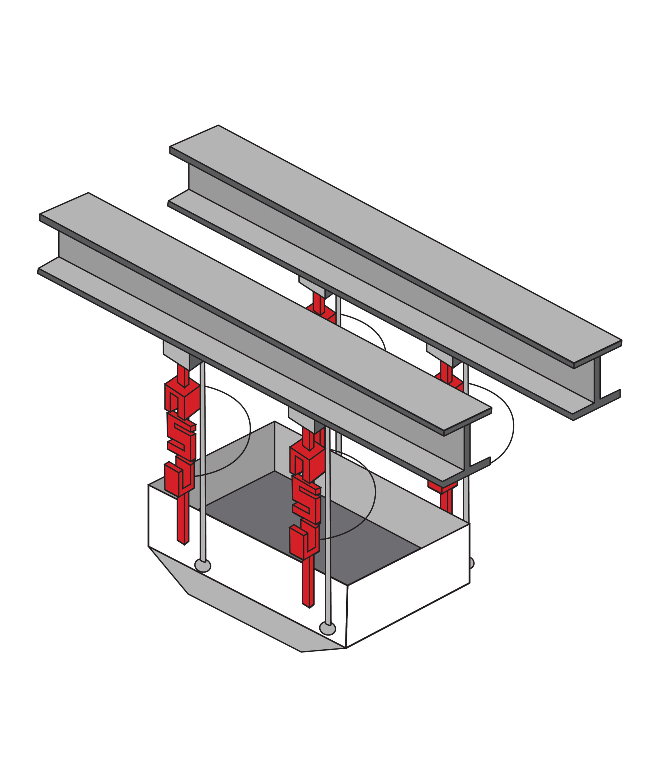
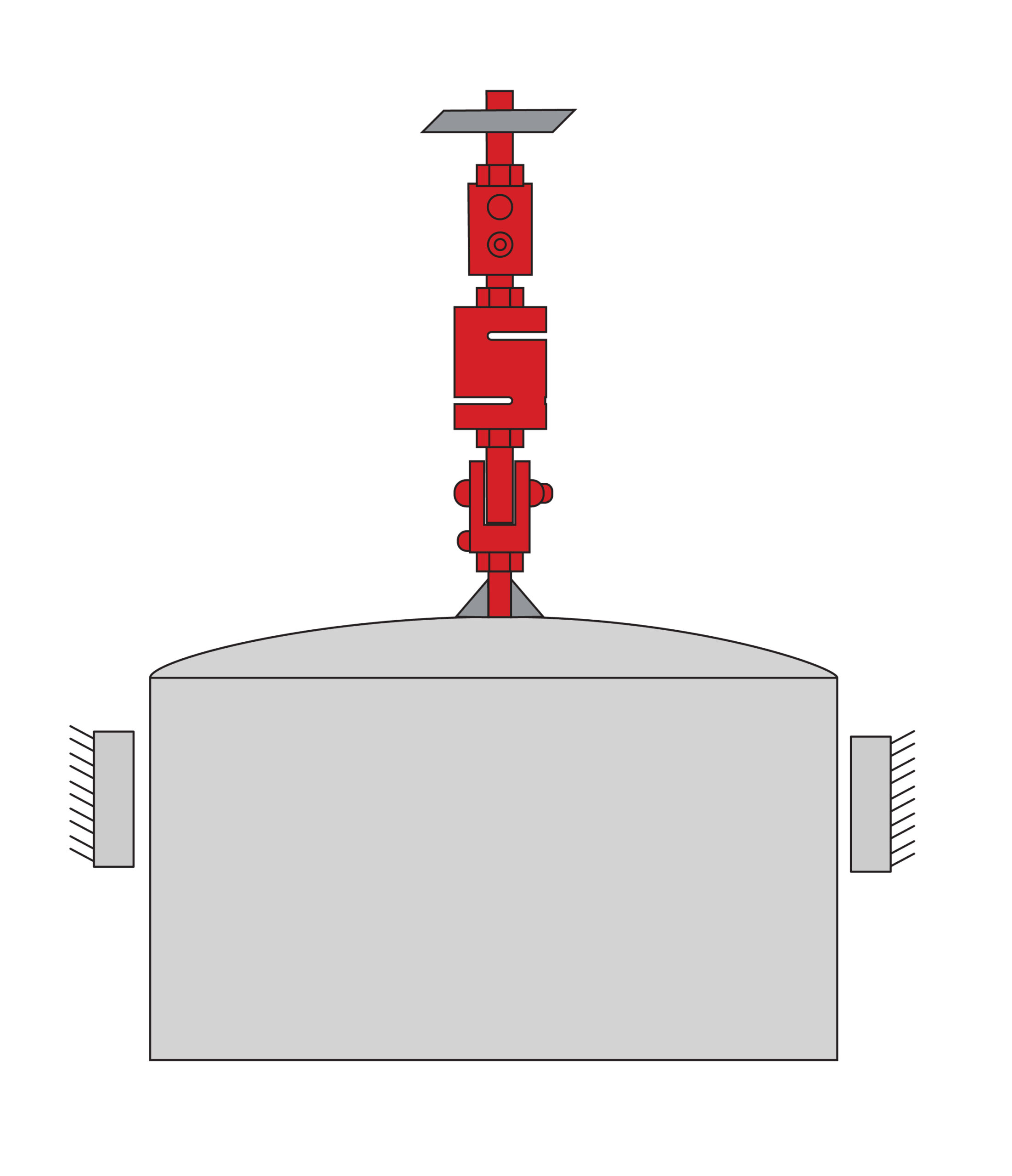
S-Type Load Cell & Module
Ideal for suspended hopper applications where tension-based weighing is preferred. Typically used when a hopper is part of a larger scale process line, otherwise compressive loading is more cost effective and simpler to implement.
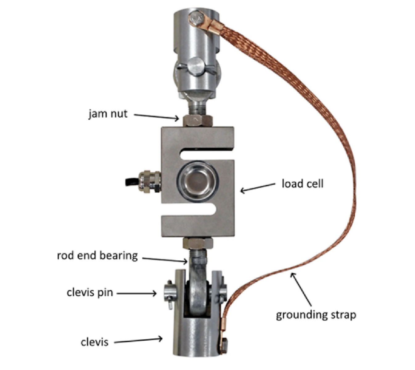
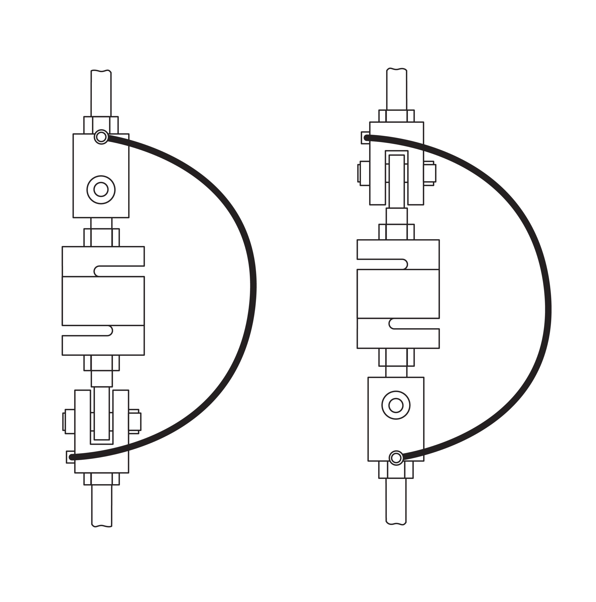
Tension weigh modules have more components than compression weigh modules as illustrated in Figure 3. The additional components are simply due to the nature of s-type load cell design with threaded fixtures to attach the load element, often incorporating spherical rod end bearings or a ball-and-cup style mounting.
Capacity Selection
For a simple static vessel weighing application, the capacity range for each load cell can be roughly approximated using the following basic formula:
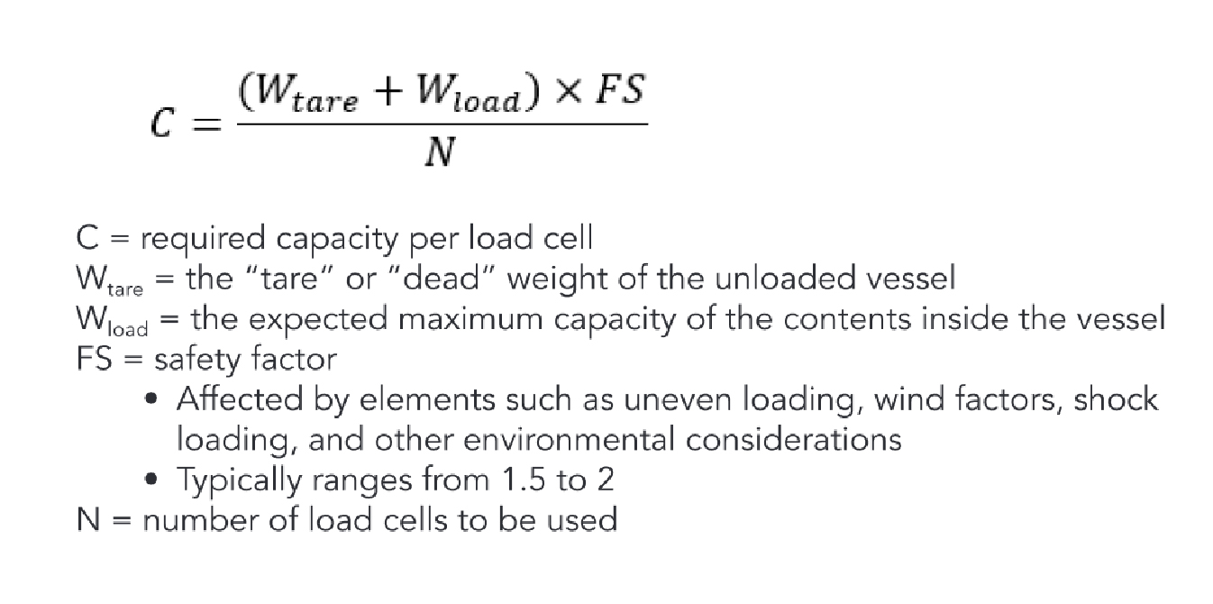
Tension weigh modules have more components than compression weigh modules as illustrated in Figure 3. The additional components are simply due to the nature of s-type load cell design with threaded fixtures to attach the load element, often incorporating spherical rod end bearings or a ball-and-cup style mounting.
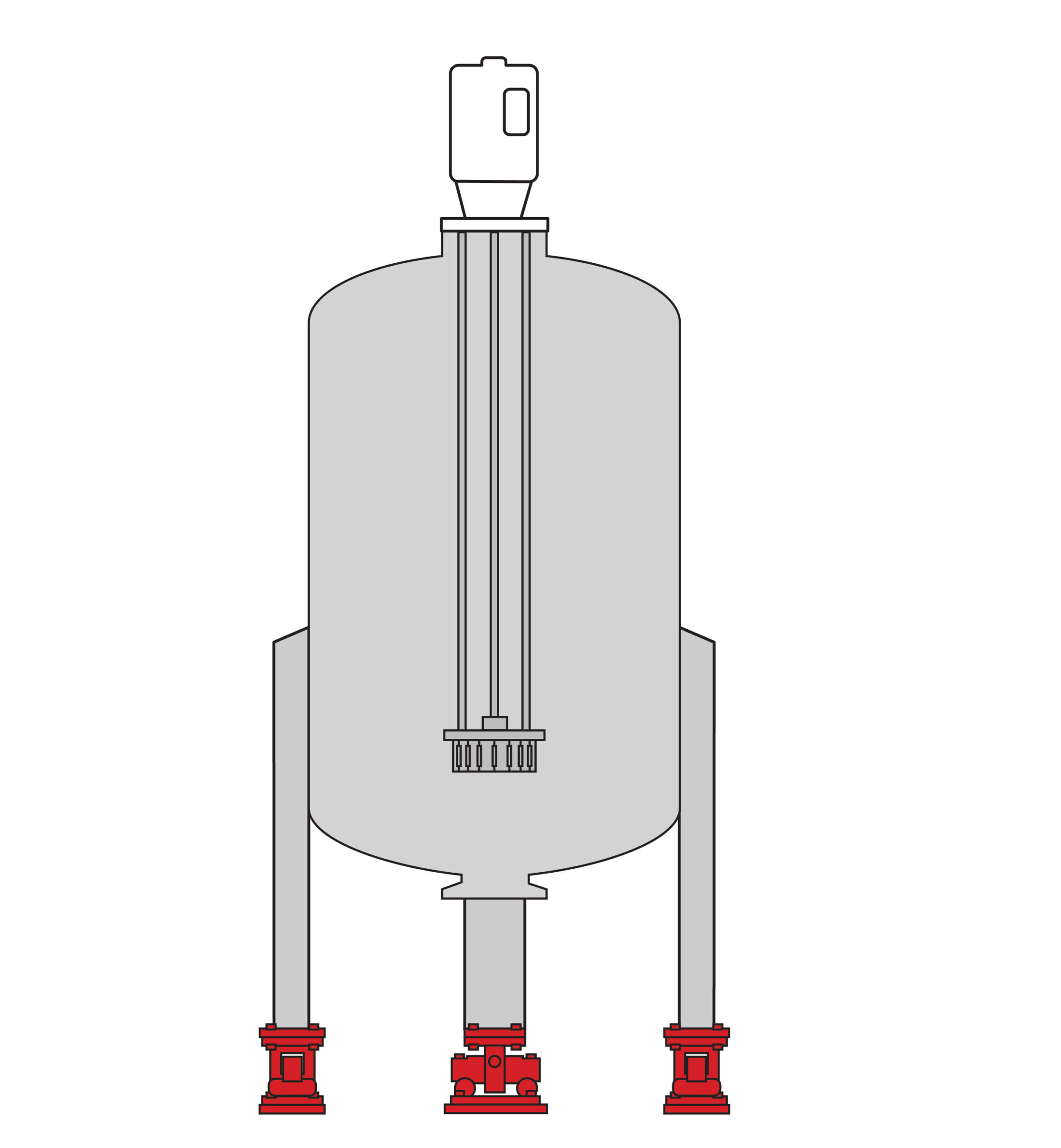
Load Cell Quantity
The number of load cells required depends on the hopper’s structural design:
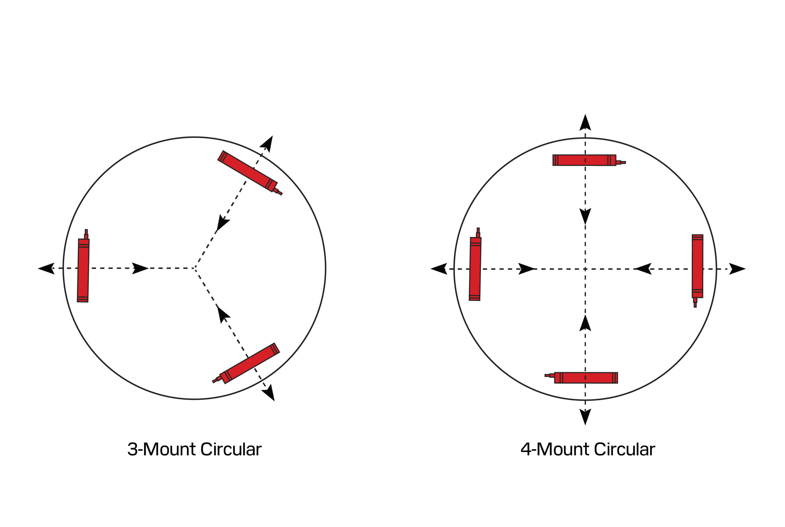
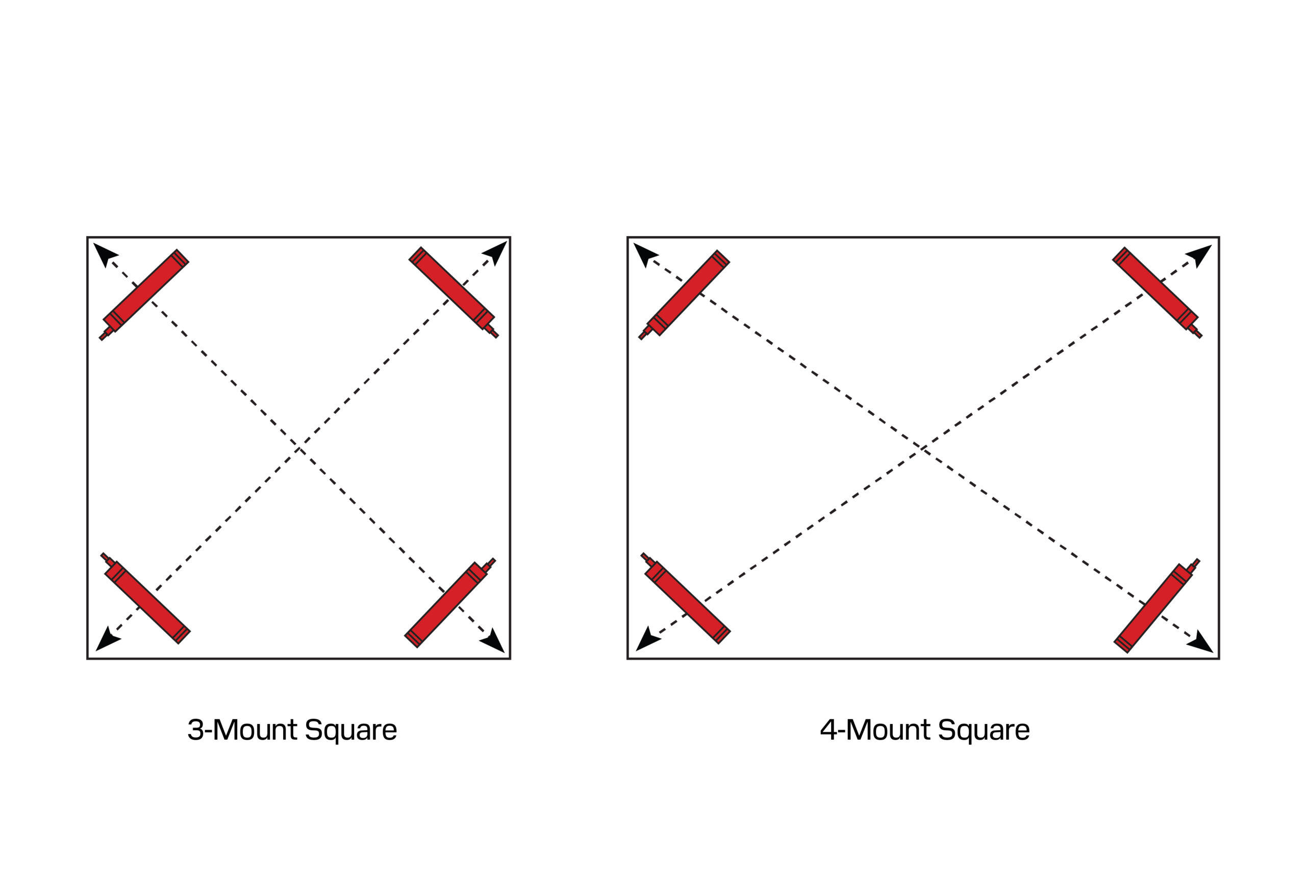
- Three load cells – Ideal for most symmetrical, medium capacity applications, providing a stable, statically determinate structure. Easier to achieve an equal load between all three load cells.
- Four or more load cells – Used for large hoppers but require precise levelling to ensure equal, statically determinate load distribution.
A statically indeterminate structure can be created by having a vessel that is too rigid, causing most of the load to fall onto just two load cells, unless the weigh modules are precisely levelled. This is typically accomplished through shims and careful measurement of each load cell’s output throughout the installation process.
Load Considerations
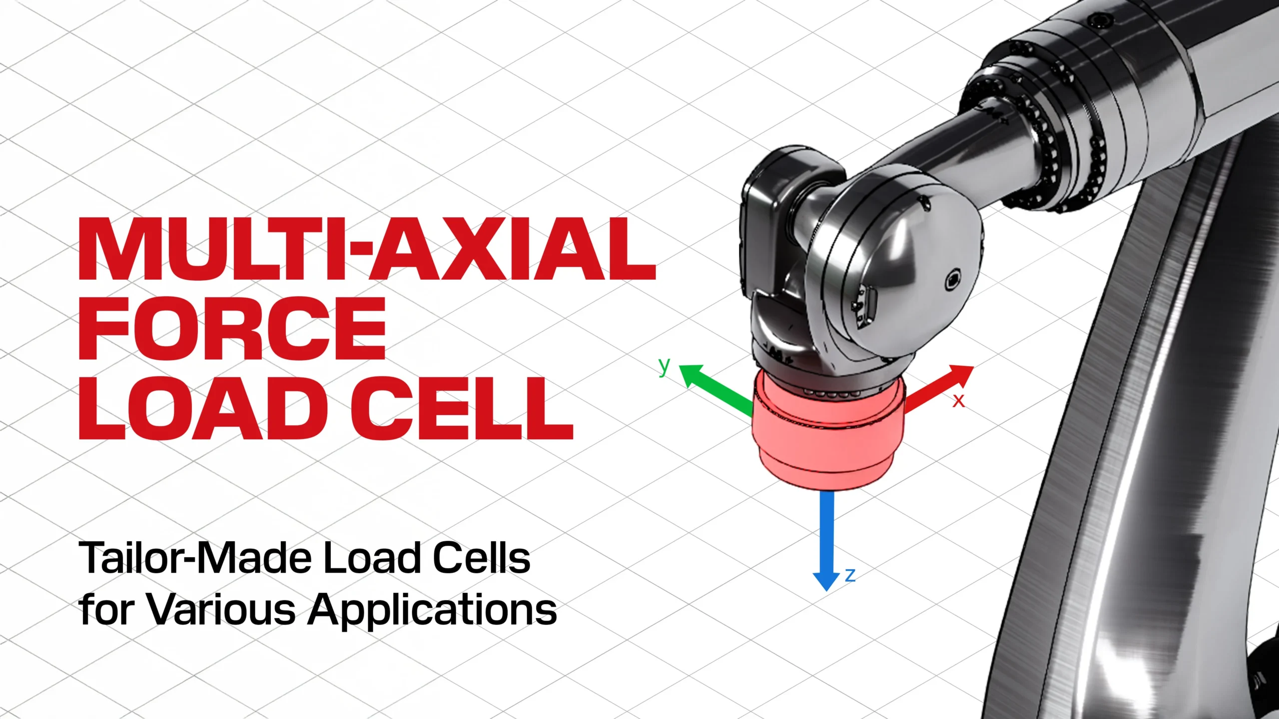
Beyond the load direction of the force applied to the cell, it’s important to consider other forces that can occur in the field. The primary objective of load cell mounts are to mitigate these forces and maintain maximum accuracy.
These additional forces include:
- Lateral forces
- Torsional moments
- Off-center/axis loading
- Additional bending moments
- Uplift forces
These factors can be influenced by thermal expansion and contraction, deflection of the structure, or other extraneous conditions. Additional considerations should be taken to protect load cells from direct sunlight, liquid contact, and submersion (i.e. pit installations).
Self-aligning load cell mounts on a rigid, level foundation should be used to compensate for minor misalignments and better absorb dynamic forces. This will allow all the applied load to be effectively transferred vertically through the load cell.
System Considerations
When integrating a load cell into a pre-existing system or designing one from scratch, it’s important to consider environmental factors, shape of the structure, and connections to the structure that may affect the performance of the load cell.
Table 1: Comparison Summary of Compression and Tension Weigh Modules
| Design Consideration | Compression Weigh Module | Tension Weigh Module |
|---|---|---|
| Floor Space | Requires floor space to accommodate the tank with additional room for mounting | Does not require floor space as the tank is suspended, allowing unobstructed movement beneath |
| Structural Restrictions | Weaker floors may required reinforcement to support the weight of a filled tank without deflection | Weaker overhead structures may require reinforcement to support the weight of a filled tank |
| Weight Limit | Generally unlimited, requires even load distribution which can be challenging with more than four points of contact | Typically does not exceed 10t (20,000lb) due to structural constraints and load cell capacity ceilings |
| Load Cell Alignment | Designs may vary, must consider floor deflection, available support structures, and tank shape/size | Alignment is less critical as tension rods and supporting structures naturally accommodate most deflections |
Key Takeaways:
- Compression weigh modules are preferred for large or heavy tanks and offer better stability and accessibility
- Tension weigh modules are space-saving and self-aligning, but structural limitations and environmental factors must be considered.
- Environmental influences like vibration, wind, and seismic forces impact both configurations differently.
These factors should be evaluated carefully to ensure proper load cell selection, structural reinforcement, and system performance.
External Connections and Piping
For a typical precision weighing application, the weighing vessel should be free from its surroundings, however many vessel weighing applications will involve other process containers connected, which can apply uneven loads or stresses. Careful consideration of piping, junctions, and connections to and from the vessel are essential to factor into the system accuracy to ensure conformance to requirements.
Stiffness of Pipes
Pipes that are suspended from the ceiling or connecting multiple vessels can exert unintended forces on a weighing system, depending on the rigidity of the connection, the pipe’s structural stiffness, and the presence (or lack) of compensating elements.
✓ Rigidly installed pipes are often considered part of the vessel’s tare weight and may not introduce significant measurement errors if their force contribution remains constant.
✖ Pipes with variable force effects due to thermal expansion, shifting loads, or structural movement can cause non-repeatability and hysteresis errors, degrading system accuracy.
✓ The impact increases with the number of connected pipes, as each additional connection introduces another potential force transmission path to the load cells.
Thermal expansion can be roughly estimated using the following formula:
ΔT = αLΔT
α = Material thermal expansion coefficient
L = Length of the component
ΔT = Variation in temperature
As different materials have different coefficients, mismatches in thermal expansion coefficients of connected components (i.e. the vessel piping, support structure, load cell, etc.) can further induce internal stresses in environments with high temperature variation. A fully rigid coupling can also induce horizontal stresses due to thermal expansion.
Pipe Friction
Pipe friction occurs at all mounting points along the pipe, particularly where pipes connect to the vessel, support structures, or adjacent equipment. Forces introduced by pipe supports, structural movement, or environmental factors can create unintended mechanical interference that distorts weight readings.
Key Sources of Pipe-Induced Force Transmission:
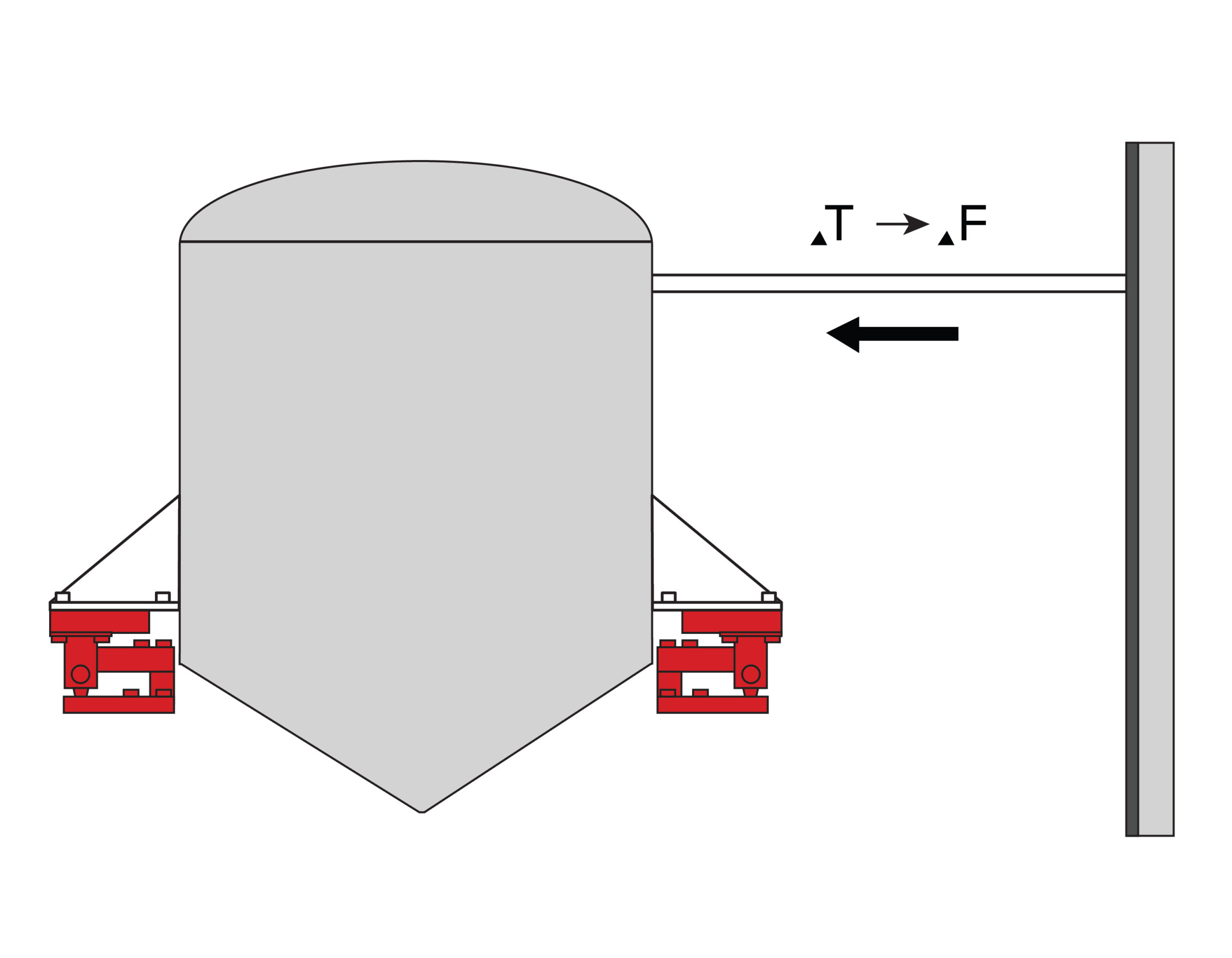
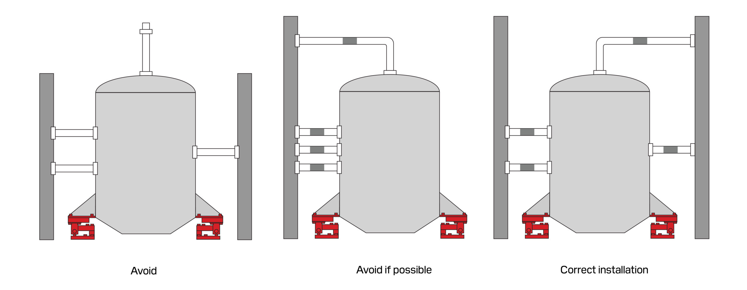
- Overhead-supported pipes – Pipes braced to building structures (e.g., ceilings, roof supports, overhead beams) can exert unintended vertical or lateral forces on vessels if deflection occurs due to snow loads, heavy rain, wind, debris accumulation, or building movement.
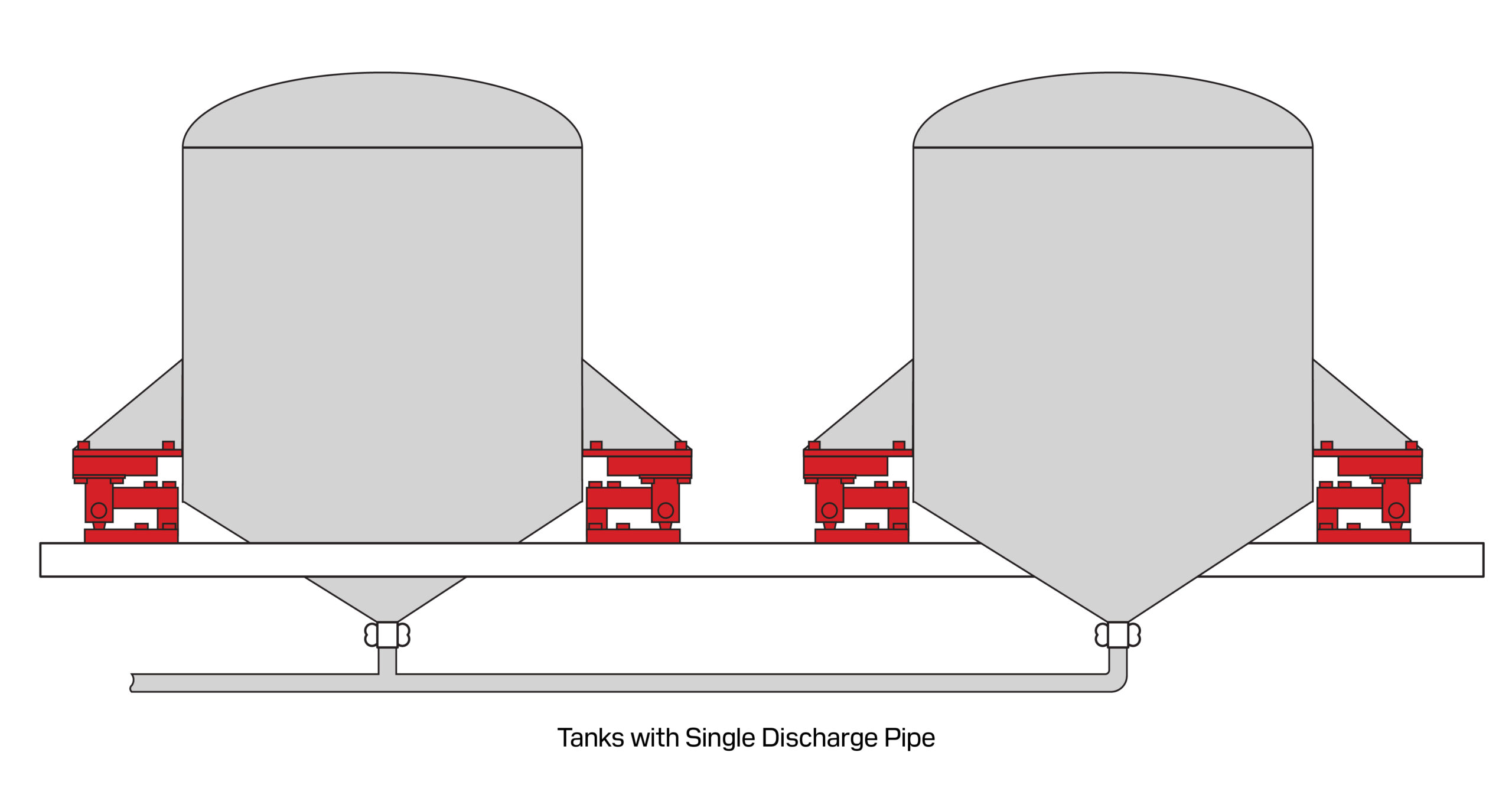
- Rigid piping between adjacent vessels – When multiple vessels are connected by rigid piping, forces from thermal expansion, structural deflection, or vessel settling can be transmitted between them, creating cross-talk that leads to measurement errors.
- Platform or support deflection – In facilities where tanks or hoppers are mounted on elevated platforms or mezzanines, structural flexing under load may transfer stress to connected piping, causing shifting weight readings as the platform settles or deforms.
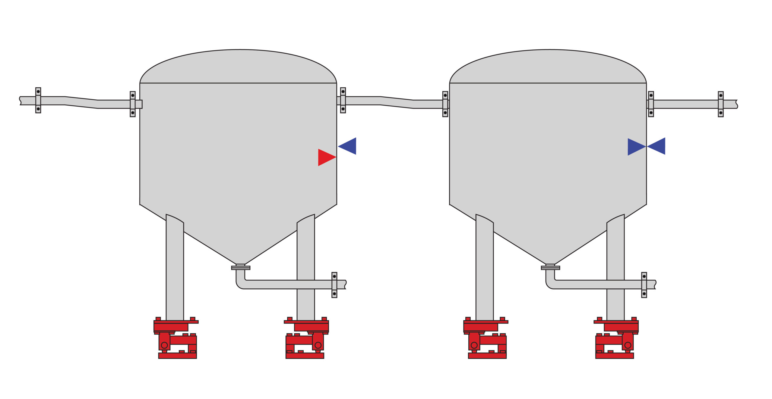
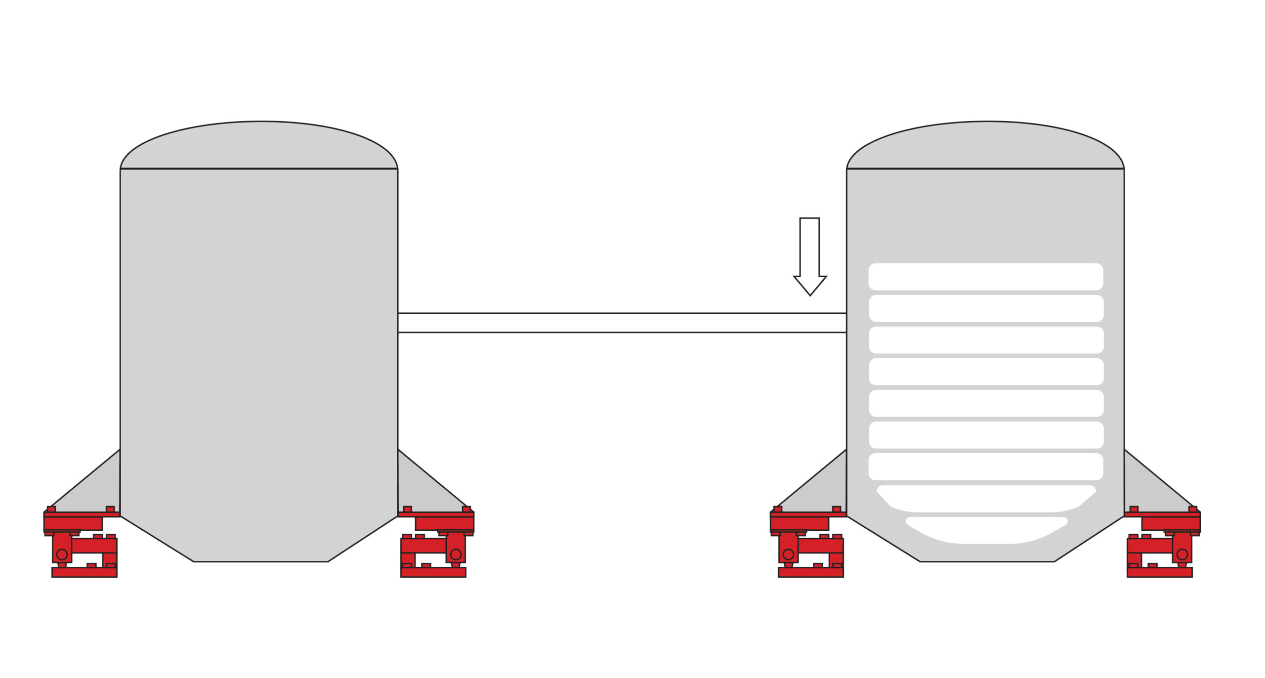
Key Consideration: Joined feed or discharge pipes without additional supports can unevenly distribute forces onto one vessel, leading to inaccurate weight readings or cyclic stress leading to premature failure.
Preventative Measures and Compensation
If pipe-induced forces remain within acceptable limits for system accuracy, additional compensation may be unnecessary. However, when piping forces exceed allowable error tolerances, the following corrective measures should be implemented:
- Reduce Pipe Influence at the Source
- Minimize pipe length – To reduce mechanical leverage on the vessel but balance against increased sag due to dead weight, which can also introduce misalignment.
- Decrease clamping rigidity – Where practical, allowing minor movement at pipe supports to prevent force transmission to the vessel.
- Ensure Symmetrical Pipe Connections – To distribute forces evenly and avoid introducing static imbalance to the vessel support.
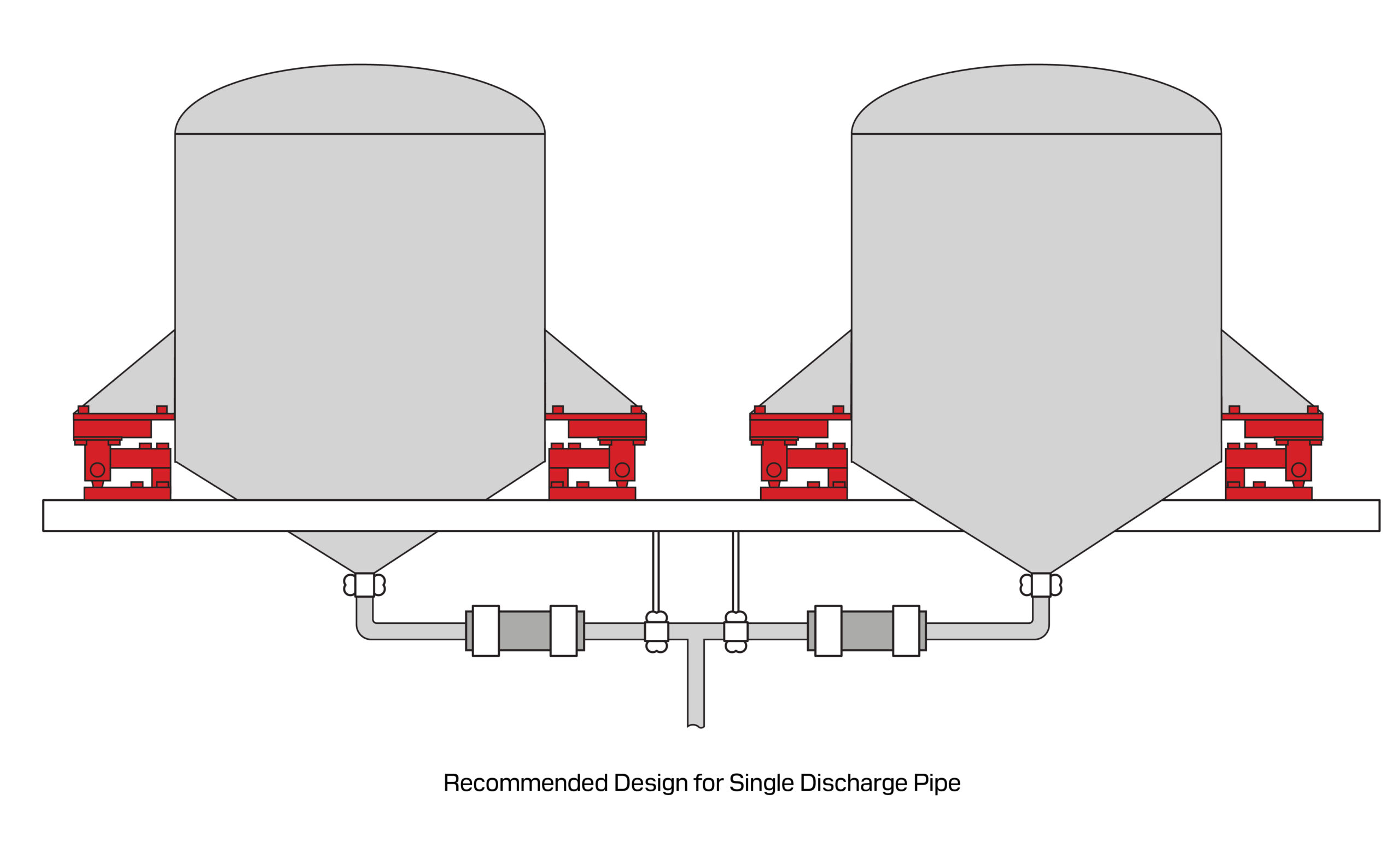
2. Introduce Flexible Compensation Elements
When pipe forces exceed acceptable tolerances, compensation methods must be integrated into the piping design.
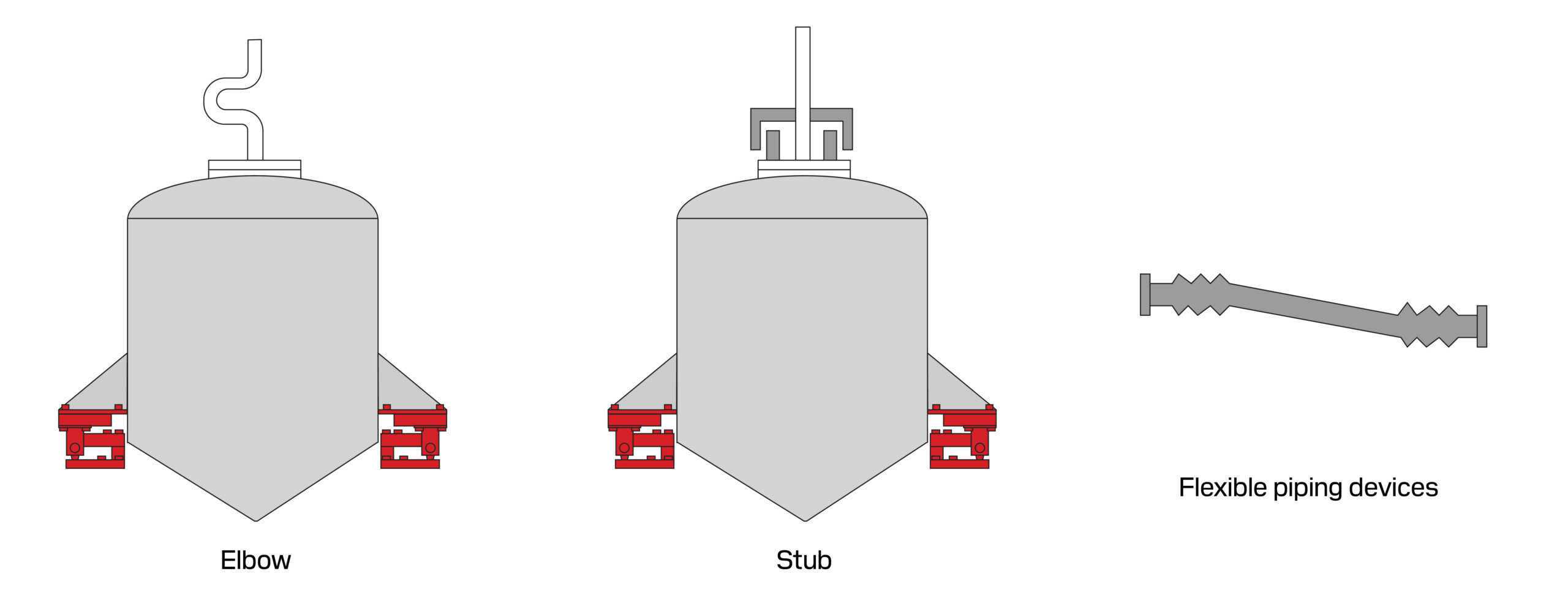
- Flexible Non-Metallic Joints – Used for applications without high pressure or temperature constraints, these provide excellent vibration isolation, fatigue resistance, and corrosion mitigation, reducing the risk of mechanical force transfer.
- Expansion Joints & Bellows – Designed to absorb thermal expansion and contraction, preventing unwanted force paths from forming. However, in pressurized systems, vertically installed bellows can introduce significant downward force, distorting weight readings.
- Pipe Stubs & Clamps – Installed to absorb minor displacement and stress relief, particularly in rigid piping systems that cannot otherwise accommodate movement.
- U-Shaped Pipe Bends – Effective in large-displacement systems where even small mechanical forces can significantly impact weight accuracy, particularly in low-capacity vessel weighing applications.
3. Design Considerations:
- Vertical bellows in pressurized systems – Must be evaluated for their force contribution to the load path, as their expansion can simulate additional weight on the vessel.
- U-bends provide passive displacement compensation – Making them critical for high-precision weighing systems where even minor piping forces introduce measurable errors.
- Multiple compensators can be integrated into a single system – Their design must not be relied upon to correct large initial misalignments, as excessive deformation will alter stiffness characteristics and reduce long-term performance.
These considerations become particularly critical in high-precision or legal-for-trade applications, where even minor external force contributions can introduce significant measurement errors and compliance issues.
Conclusion
Different manufacturers and resellers have varied methodologies for providing load cell specifications. As such, there can be significant differences in how the data should be interpreted. Some may rely on theoretical calculations or industry-standard benchmarks, while others might derive information from more rigorous live testing.
At ANYLOAD, we distinguish ourselves by only providing data that we have proven through extensive live testing using our comprehensive array of equipment. This approach ensures that our specifications are accurate and reliable, reflecting more accurately real-world performance rather than theoretical assumptions.
Additionally, in scenarios where there is uncertainty or a high risk of error, we may understate our figures. This conservative approach provides our customers with an added layer of security, ensuring that our load cells perform reliably even in the most demanding conditions. By prioritizing accuracy and reliability, we help our customers achieve precise and dependable measurements in their applications.