


배선 가이드
로드셀은 물리적 힘을 전기 신호로 변환하는 방식으로 작동하며, 이 과정에서 전원이 필요하고 로드셀의 케이블을 통해 신호가 출력됩니다. 이 케이블은 로드셀의 생명줄로, 일반적으로 보호 피복에 싸인 여러 색상의 전선으로 구성됩니다. 주요 역할은 로드셀을 정션 박스, 디지털 표시기 또는 기타 계측기와 같은 외부 장치에 연결하여 로드셀에 전원을 공급하고 처리 및 표시를 위한 측정 데이터 전송을 용이하게 하는 것입니다.
표준 로드셀은 일반적으로 광범위한 측정 시스템에 통합할 수 있도록 개방형 케이블 와이어로 끝나는 아날로그 신호 출력을 제공합니다. 이러한 개방형 케이블은 유연하게 연결할 수 있지만 적절한 설정을 위해서는 전기 배선에 대한 기본적인 이해가 필요합니다.
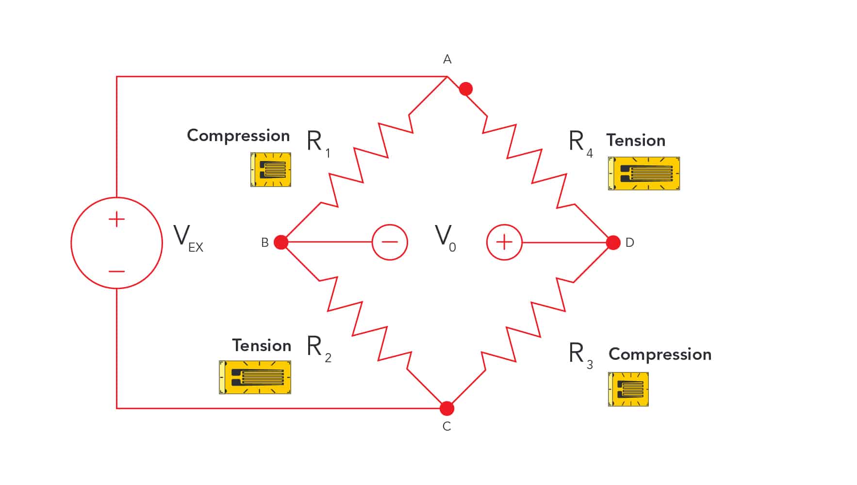
이 케이블에는 일반적으로 로드셀의 기능에 필수적인 두 쌍의 전선, 즉 여기 전선과 신호 전선이 들어 있습니다. 여기 와이어는 로드셀 내의 휘트스톤 브리지 회로에 전원을 공급하고 신호 와이어는 기계적 변형으로 인한 전기 출력을 전달합니다. 대부분의 표준 로드셀 애플리케이션에서는 중요하지 않지만 경우에 따라 감지 와이어도 포함될 수 있습니다.
참고: 일부 로드셀에는 특정 용도나 환경에 맞는 특수 커넥터가 있을 수 있습니다. 자세한 지식이나 제조업체의 지침 없이 이러한 커넥터를 변경하거나 인터페이스하면 로드셀의 무결성과 기능에 위험이 발생할 수 있습니다.
2. 로드셀 케이블의 해부학
로드셀 케이블은 혹독한 산업 환경을 견딜 수 있도록 설계되며, 일반적으로 내부 전선을 물리적 및 환경적 손상으로부터 보호하는 내구성 있는 고무 또는 PVC 피복으로 싸여 있습니다. 이 보호 외피 안에는 로드셀 내에서 각각 특정 기능을 수행하는 4~6개의 멀티 컬러 와이어가 있습니다. 이 전선은 전자기 간섭을 방지하기 위해 차폐되어 있습니다.
실용적인 관점에서 로드셀을 연결할 때는 전선 끝과 연결하려는 터미널 또는 장치 사이에 적절한 금속 대 금속 접촉이 이루어지도록 하는 것이 필수적입니다. 즉, 전선 자체에 손상을 주지 않으면서 안전한 연결을 위해 절연체를 조심스럽게 벗겨내어 도체를 충분히 노출시켜야 합니다. 연결 상태가 양호해야 전력과 신호를 안정적으로 전송할 수 있으며, 연결 상태가 느슨하거나 불량하면 부정확한 판독값이 나오거나 간헐적인 신호 손실이 발생할 수 있습니다. 또한 로드셀의 오작동 또는 손상으로 이어질 수 있는 배선 오류를 방지하기 위해 적절한 커넥터를 사용하고 제조업체에서 지정한 배선 색상 코드를 따르는 것이 좋습니다.
참고: 배선 색상 코드는 제조업체마다 다를 수 있습니다. 항상 사용 중인 로드셀의 특정 데이터시트 또는 보정 인증서를 참조하세요.
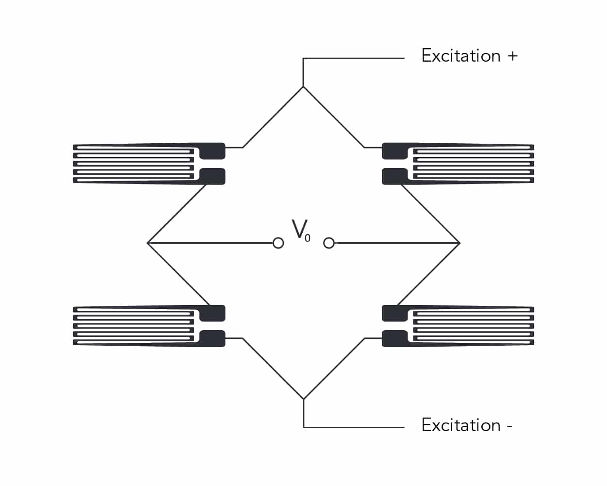
3. 여기 전선
여기 와이어는 휘트스톤 브리지 회로가 작동하는 데 필요한 전기 에너지를 공급함으로써 로드셀의 기능에 중요한 역할을 합니다. 일반적으로 로드셀은 정확한 힘 또는 무게 측정을 위해 안정적이고 정밀한 여기 전압이 필요합니다. 변동은 출력 신호의 변화로 이어져 측정의 신뢰성에 영향을 미칠 수 있으므로 이 전원 공급 장치의 일관성이 중요합니다.
5-10V는 대부분의 로드셀에 전달되는 일반적인 여기입니다.
흥분 + (약어: VCC 또는 EXC+)
여기 - (약어: GND 또는 EXC-)
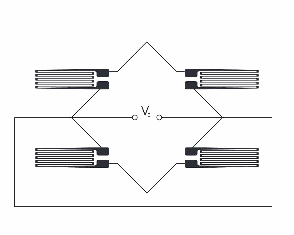
4. Signal Wires
Signal wires within a load cell cable are essential for transmitting the electrical signals generated by the strain gauges as they respond to mechanical forces. These wires carry the analog signals that represent the precise measurements of weight or force from the load cell to the readout indicator or data acquisition system.
Analogue load cell signals are generally measured as a fraction of the excitation voltage being delivered. This is referred to as the load cell’s signal output and is denoted in millivolts per volt (mV/V).
Most standard load cells in the weighing industry are 2.0mV/V or 3.0mV/V.
Signal + (abbrev: OUT+ or SIG+)
Signal – (abbrev: OUT- or SIG-)
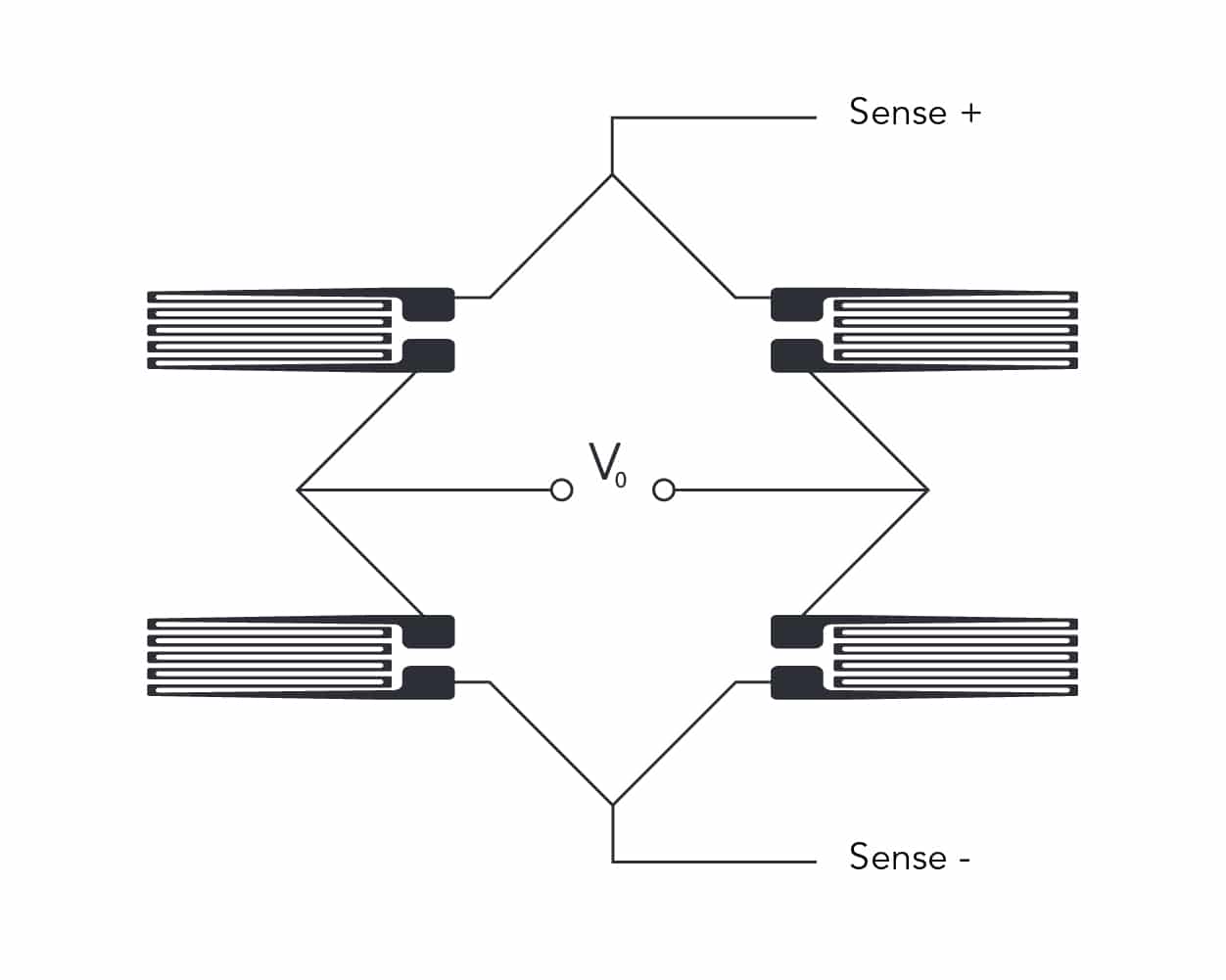
5. Sense Wires
Sense wires in load cell systems enhance accuracy in scenarios with extended cable lengths or where very significant temperature shifts can affect performance. Often included in 6-wire configurations, these wires create a feedback mechanism for the excitation voltage, compensating for resistance changes in signal and excitation wires due to varying cable lengths (>20m or 65ft).
Connected to the load cell’s excitation and signal terminals on the instrument side, sense wires allow for real-time adjustments to the voltage at the load cell, stabilizing the excitation voltage.
However, for most applications, sense wires are unnecessary. Load cells are typically calibrated to standard cable lengths during manufacturing, and in practical settings, they are usually linked to a junction box, from which any long-distance cabling extends. Since junction boxes include sense wire connections, the direct long-distance wiring of a single load cell exceeding 20m (65ft) is very rare.
EXAMPLE: If an indicator delivering 10V to the load cell, generates a return signal of 2.0 mV/V, a drop in the actual excitation voltage reaching the load cell over a 30m distance down to 9.98V could compromise the measurement accuracy
6. Shielding
The shield within a load cell cable acts as a barrier against electromagnetic (EMI) or radio-frequency interference, which can distort the analog signals of a load cell. It is typically a conductive layer of braided copper or aluminum foil, that encases the inner wires.
The shield is grounded at one end, usually at the point of signal interpretation or data acquisition, creating a path for any intercepted interference to be safely diverted. This grounding is essential in maintaining the clarity and accuracy of the measurements by preventing noise from contaminating the signal. Proper installation and grounding of the shield are key to ensuring the effectiveness of this protective layer, especially in electrically noisy industrial environments.
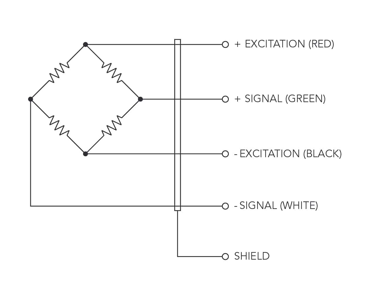
7. Connection Load Cell Wires
Connecting Load Cell Wires to Terminals
Ensuring a secure connection of load cell wires to the terminals of a junction box, indicator, or data acquisition system is crucial for the accurate transmission of signals. Firstly, identify each wire within the load cell cable based on its designated function and color coding — typically including excitation (+ and -), signal (+ and -), and potentially sense (+ and -) wires. Always refer to the load cell’s specific wiring diagram to accurately match each wire to its corresponding terminal.
Each wire should then be securely fastened to its respective terminal within the junction box or indicator. Terminals are often clearly labelled with “+/-” signs for excitation and signal connections, and possibly separate inputs for sense wires if applicable.
The bare wire should be in full contact with the terminal, held tightly by screws or clamps, ensuring a stable electrical pathway. This is vital to prevent any signal loss, resistance increase, or intermittent connections that could lead to inaccurate readings. In environments prone to vibration or movement, consider using locking washers or thread-locking fluid to prevent connections from loosening over time.