


용기 계량 - 설치
마지막 업데이트 날짜 - 15분 읽기
Installing a vessel weighing system (whether for a tank, silo, hopper, mixer, or reactor) requires more than simply placing load cells beneath a structure. Even the most carefully designed system can suffer from inaccurate readings, premature component wear, or operational instability if improperly installed. Successful implementation demands attention to alignment, levelling, mechanical isolation, and proper force introduction, all while accounting for real-world factors such as thermal expansion, vibration, and structural movement.
Unlike standard platform scales, vessel weighing installations must be integrated into existing or purpose-built infrastructure, often with constraints related to access, available space, and process piping. Factors such as load path clarity, support point rigidity, and electrical signal integrity all influence final performance. Poor installation compromises accuracy and can increase the risk of load cell failure or costly downtime.
This section provides practical guidance for the installation phase of vessel weighing systems, offering generalized best practices and critical checkpoints to help ensure that the system performs as intended under actual operating conditions.
General Considerations
Vessel weighing systems are essential across industries The following best practices apply to all weigh module installations, regardless of vessel type or configuration.
This Application Note is intended as an educational aide to orientate engineers, site managers, and technicians on the general installation process of vessel weighing applications. Proper adherence to these guidelines help to ensure a stable, accurate, and long-lasting weighing system, but installers must refer to system-specific documentation for all projects.
Qualified Personnel Only
- All installation work should be performed only by trained and qualified personnel familiar with the mechanical, electrical, and environmental parameters of the system.
- This is especially important for legal-for-trade installations or hazardous area classifications, where accredited/certified technicians and special equipment are generally required.
For assistance locating a qualified provider, visit our Find a Dealer page or contact us.
Site Preparation & Structural Requirements
- Ensure the foundation or support structure is properly prepared and capable of handling full vessel load without deflection or instability before beginning installation.
- Protect load cells and associated equipment from moisture, corrosive materials, extreme temperatures, mechanical damage, and debris based on environmental conditions.
Welding Precautions
- All structural welding should be completed before installing load cells.
- If unavoidable, disconnect load cells from electronics and place the ground clamp as close as possible to the weld point to avoid damaging current flow through the load cells.
Grounding and Cable Handling
- Ensure proper electrical grounding of all components.
- Do not alter load cell cable lengths, as this can compromise calibration and system performance. Excess cable should be coiled and secured, not cut.
Post-Installation Alignment Check
- Once installation is complete, verify that all modules are level and correctly aligned to share load evenly.
- This can be confirmed during the initial system calibration, which will also highlight any mechanical or load distribution issues.
Following these general principles helps ensure that subsequent installation steps, including module placement, anchoring, and calibration, are performed under ideal conditions for system reliability and accuracy.
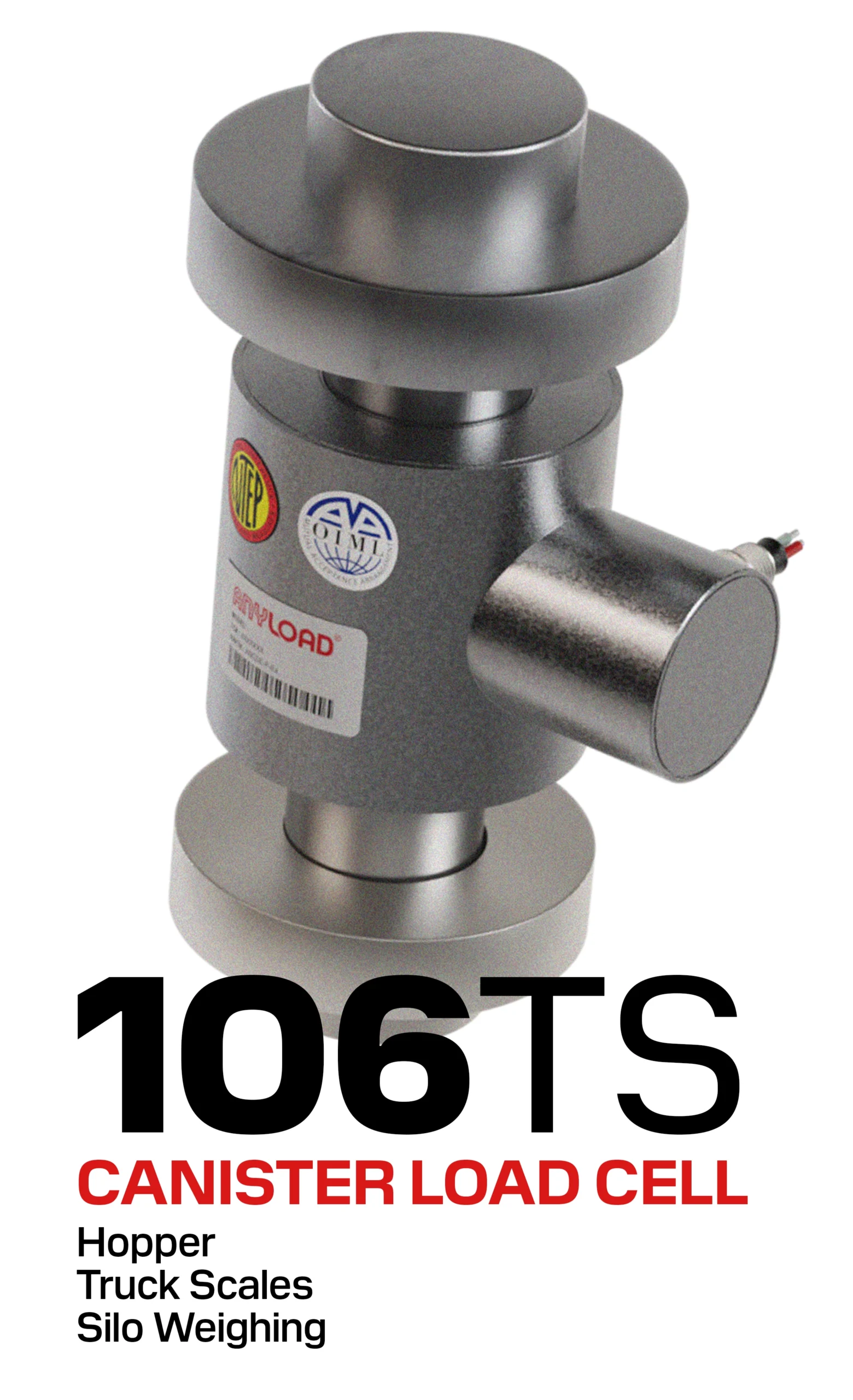
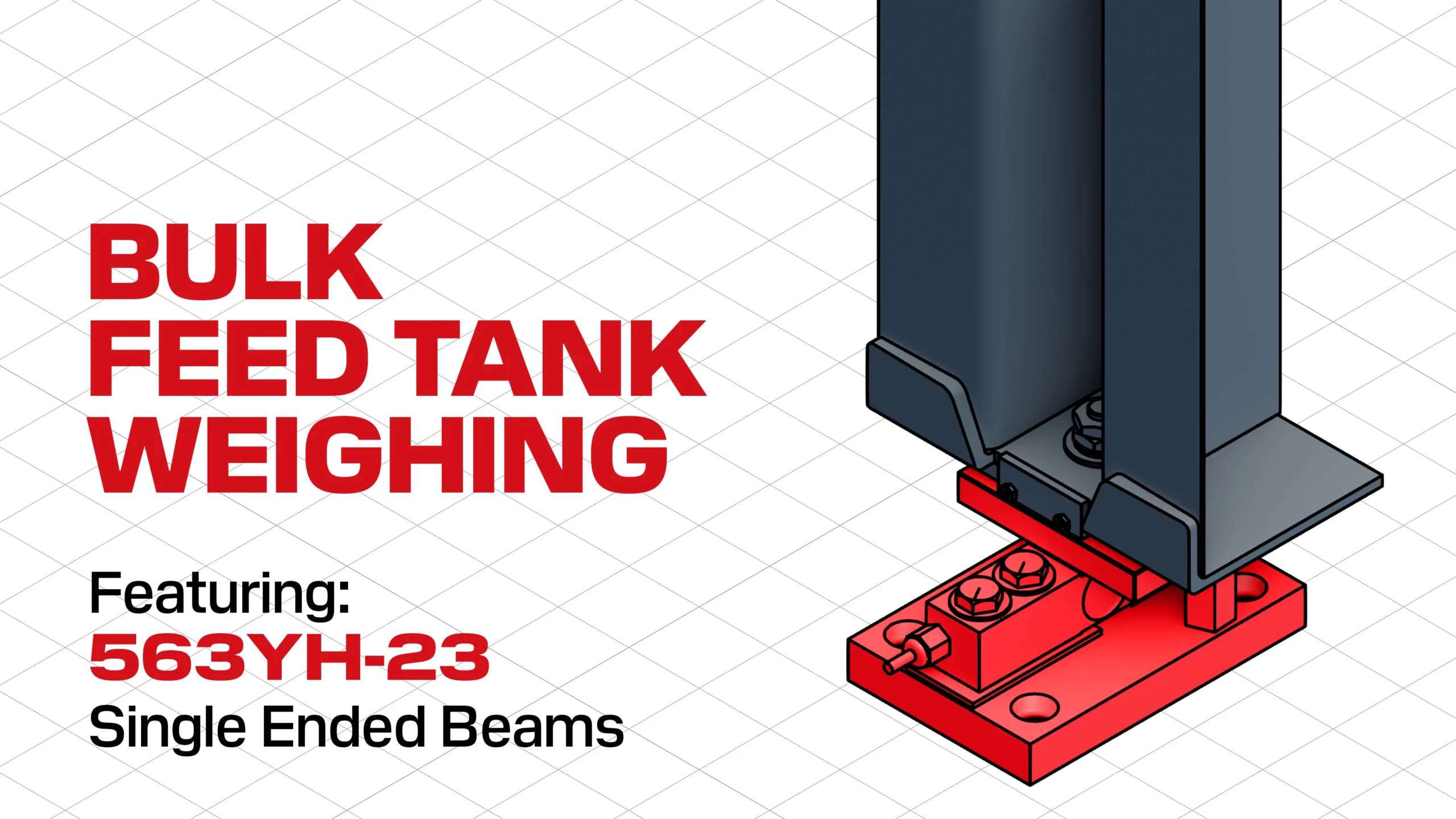
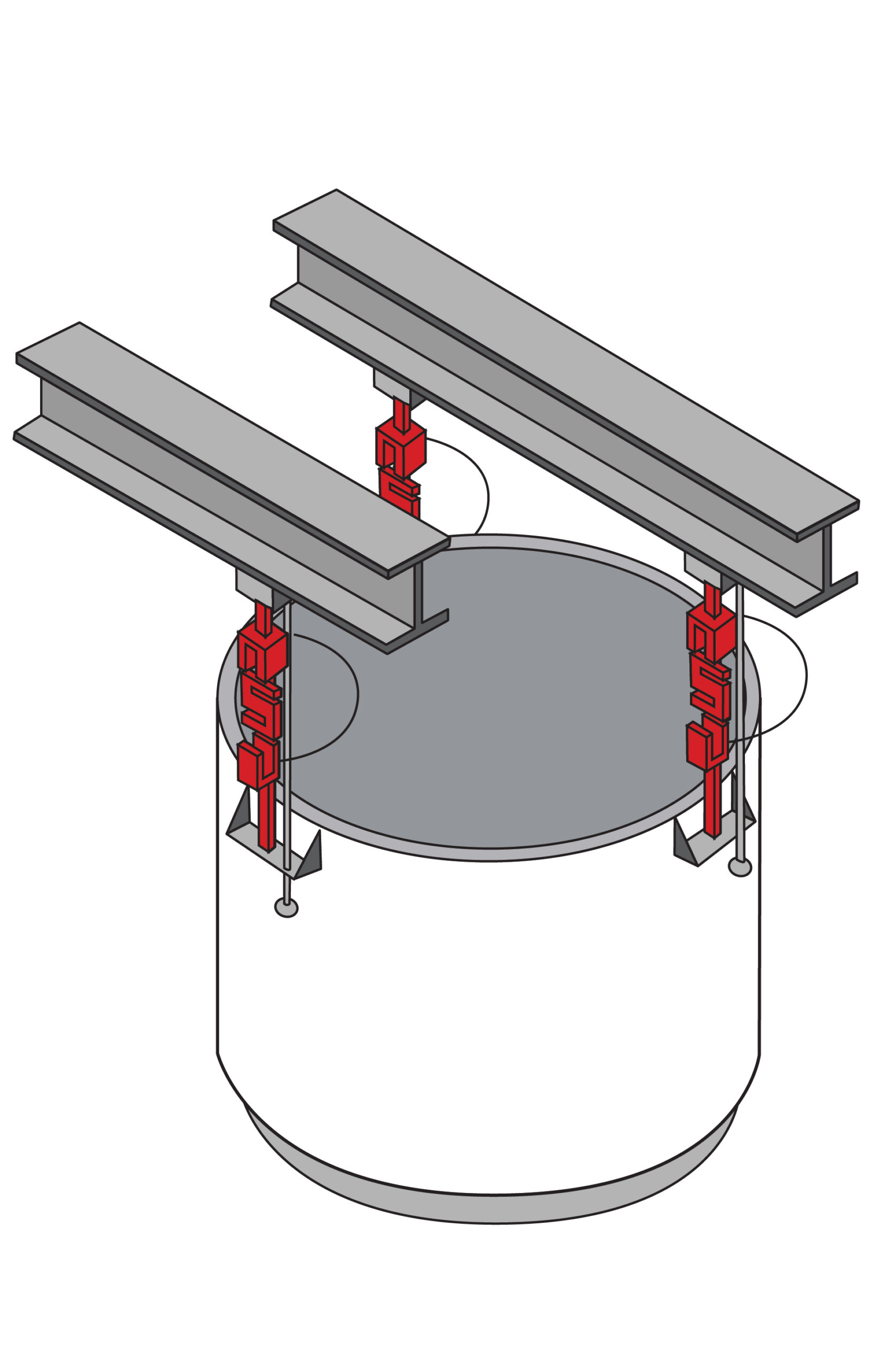
Installing Compression Weigh Modules
Compression weigh modules are the most common configuration for vessel weighing systems, offering stable support and accurate measurement by placing load cells beneath the vessel’s mounting points. Proper installation is critical to ensuring even load distribution and long-term performance.
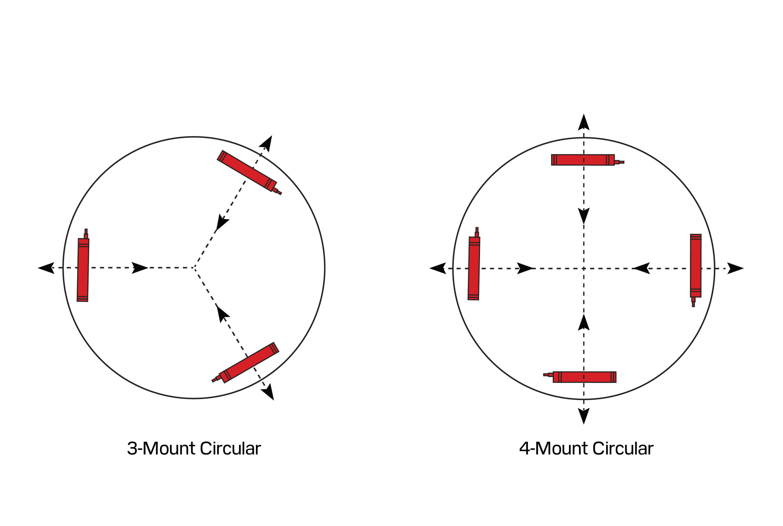
For most systems, a minimum of three modules (arranged in a triangular layout) is sufficient and simplest for levelling and load distribution. For larger or rectangular vessels, four modules in a square or rectangular pattern are typical. More than four points should only be used when unavoidable, as it introduces complexity in levelling and load distribution.
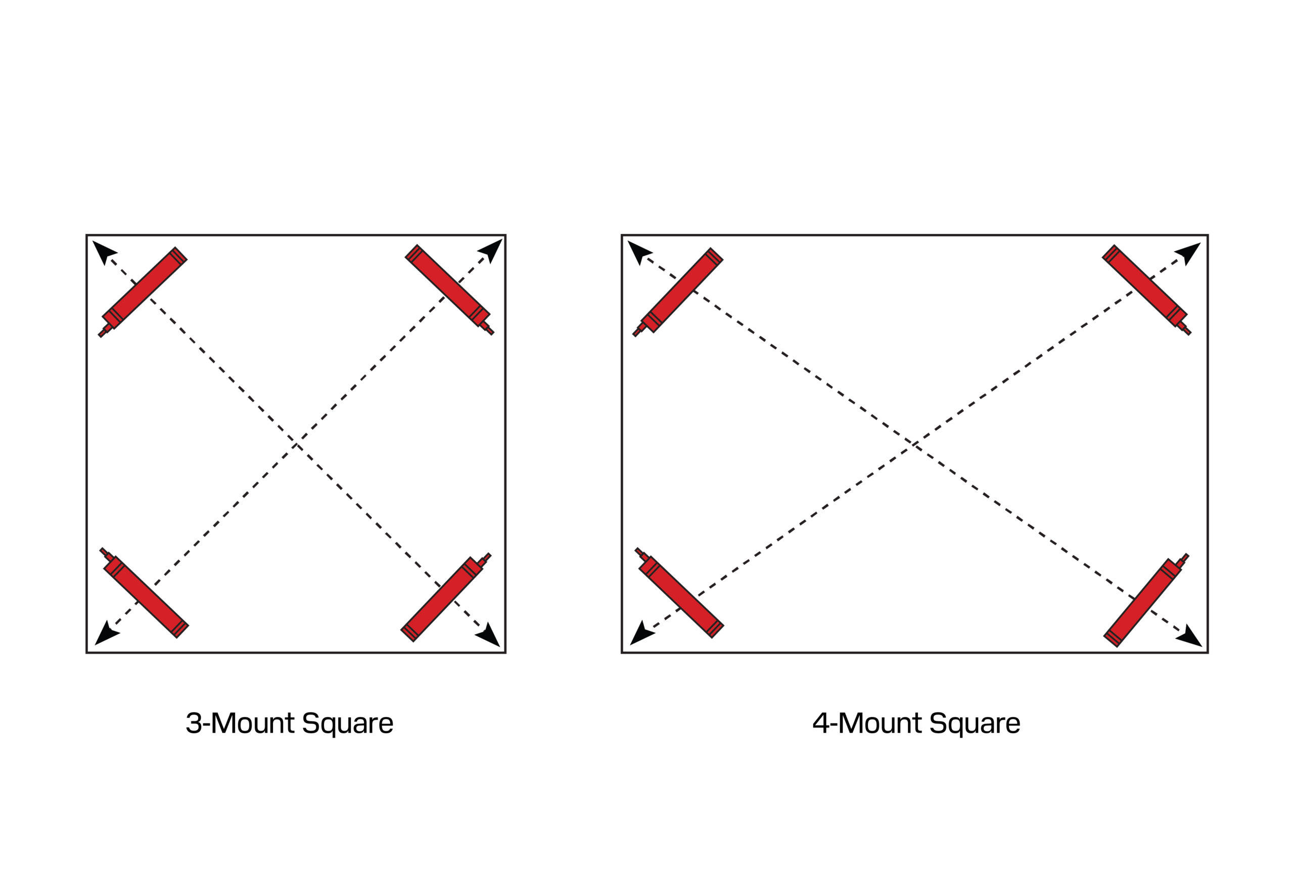
Below is a generalized orientation guide for installing compression weigh modules:
Installation Steps
1. Position and Lower the Vessel Carefully
- Place a weigh module under each tank leg or mounting bracket.
- Slowly lower the vessel onto the modules only once all are properly positioned, ensuring no module is prematurely loaded.
- Protect weigh modules during installation to prevent mechanical damage from tilting or unbalanced loading.
2. Level the Load Points Using Shims
- All top plates must be within ±0.5° of each other to prevent uneven loading.
- Add shims as needed to ensure level contact between the vessel mounting surface and top plate.
Shimming Guidelines:
Top Plates:
- Use full-plate shims to support the entire top plate, especially under the central load path.
- Partial shims may be used to fill gaps at corners or edges to ensure flush contact.
- Base Plates: Shim with steel plates or fill voids using non-shrink grout between the base plate and foundation surface.
3. Secure Anchoring
- If the application involves uplift, vibration, or side loading, ensure the anchoring method (e.g., welding, bolting, epoxy anchoring) is suitable for the maximum expected forces.
- Always follow manufacturer guidelines for anchor hole sizing, depth, and torque specifications.
4. Base Plate Alignment and Anchoring (if applicable)
- If the tank must be temporarily lifted, mark the base plate positions, drill anchor holes, and reinstall the base plates.
- After lowering the tank, re-check top plate level alignment and adjust shimming if necessary.
5. Mounting the Junction Box
- Install the junction box in a dry, splash-proof, and thermally isolated location.
- Never mount the junction box on the vessel itself, as cable tension can transfer mechanical force and affect accuracy.
- Load cell cables must not be shortened or extended—use coiled slack near the junction box if necessary.
- Custom cable lengths are available and recommended for installations with known cable routing.
6. Electrical Connections
- Wire each load cell to the junction box according to the wiring diagram and color codes provided.
- Ensure all connections are secure, shielded, and protected from moisture or mechanical strain.
7. Connect to Scale Electronics
- Route the junction box output to the weight indicator, transmitter, or scale controller, ensuring shielding and grounding are maintained to avoid noise interference.
8. Calibration
- Once mechanically and electrically complete, proceed to calibrate the system according to the indicator or transmitter instructions. Use appropriate calibration weights or simulation tools depending on system class and accuracy requirements.

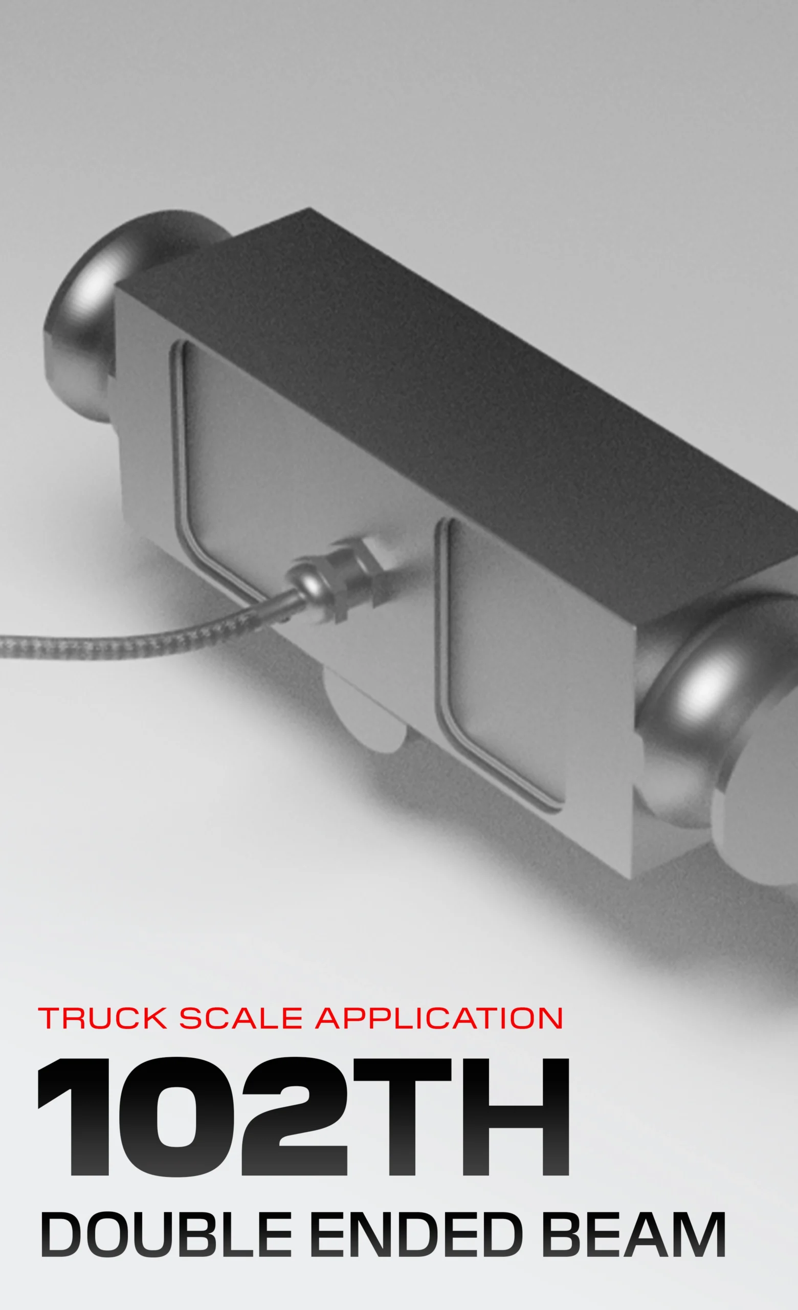
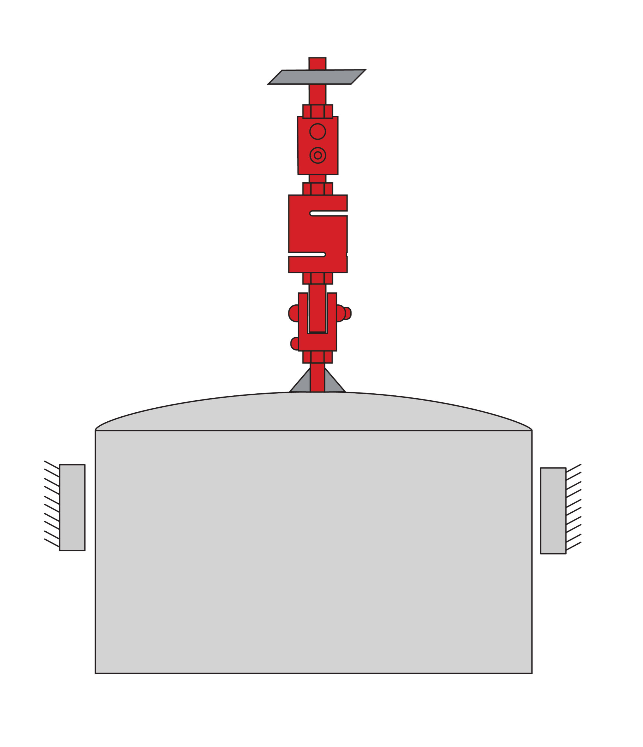
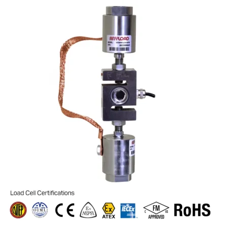
Installing Tension Weigh Modules
Tension weigh modules are commonly used for suspended vessel weighing systems, such as ingredient hoppers, suspended tanks, or reactors mounted from overhead structures. Like compression systems, a minimum of three modules is required for stability, with four-point configurations often used for larger or higher-capacity installations.
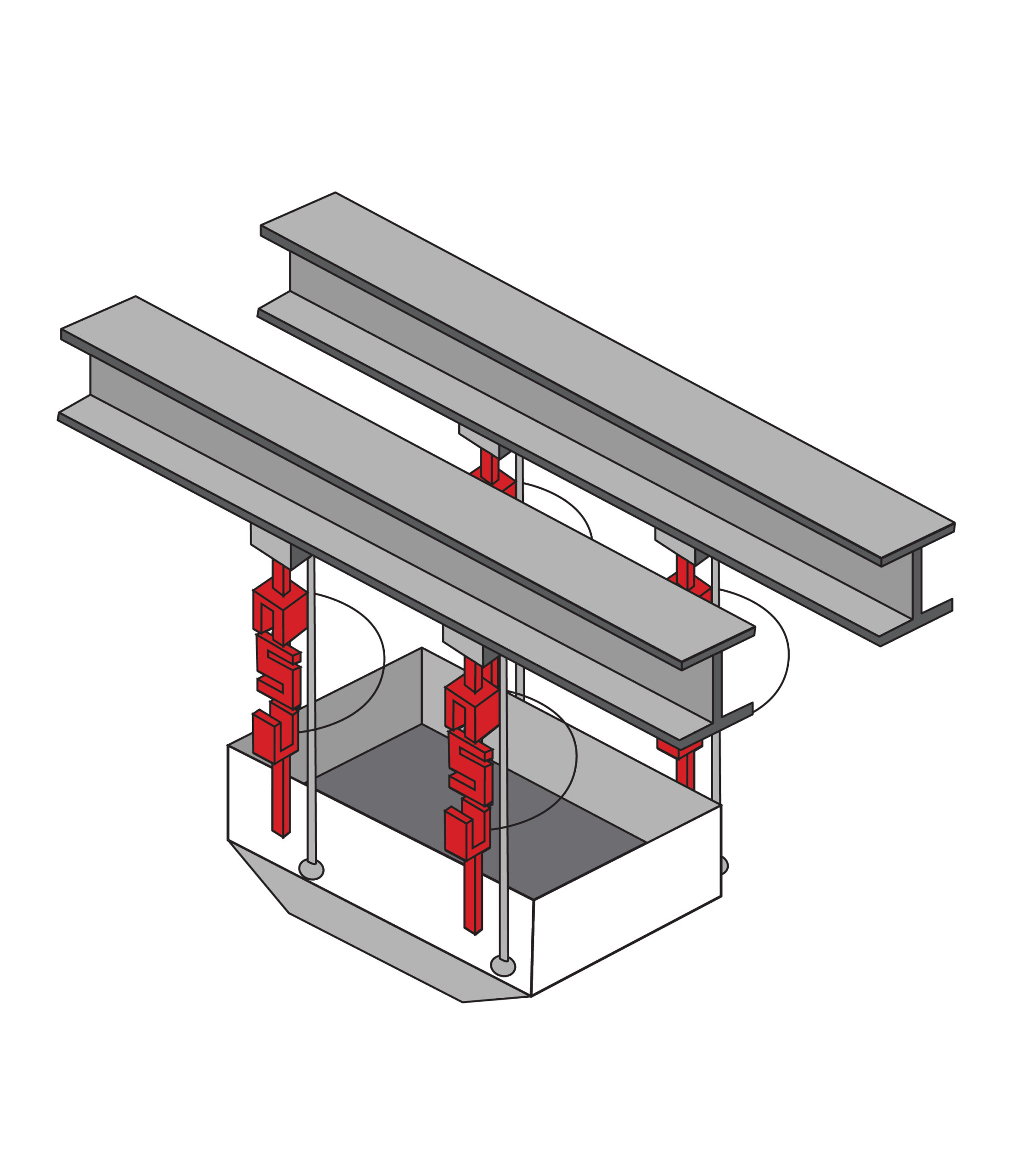
Because the vessel is suspended, tension systems are especially sensitive to structural deflection, alignment, and safety risks. It is essential that the support structure is rigid and engineered to handle the full load, and that redundant safety mechanisms (e.g., chains, backup rods) are installed to prevent catastrophic failure in the event of a load cell or connection failure.
Installation Steps
1. Mount Tension Modules & Align Supports
- Attach each S-type load cell (or equivalent tension module) to the vessel’s mounting points.
- Ensure the overhead brackets or beam connections are aligned properly to avoid introducing side loads.
- Confirm that the dead end (fixed side) is mounted to the support structure, and the live end is connected to the vessel.
2. Connect Threaded Rod to the Vessel Side (Live End)
- Use an appropriately rated threaded rod to connect the vessel-side clevis to the load cell.
- Tighten the jam nut against the clevis to prevent rod rotation or loosening during operation.
3. Secure to Support Structure (Dead End)
- On the support side, run a second threaded rod through a pre-drilled hole in the overhead bracket.
- Install a rigid backing plate, washer, and double jam nuts to lock the rod in place once the vessel’s height and level are set.
4. Install Safety Restraints
- Mount a safety rod, chain, or equivalent backup system adjacent to each tension module.
- Leave vertical clearance so that the safety device does not engage under normal operating conditions, but will catch the vessel in the event of a component failure.
5. Add Lateral Limiters (If Applicable)
- If the vessel may experience horizontal movement (e.g., due to agitation or environmental vibration), install check rods or bumper bolts to limit lateral displacement.
- Ensure these horizontal restraints do not interfere with vertical motion, allowing the weigh modules to operate freely.
6. Mount the Junction Box
- Place the junction box in a dry, heat-protected location, separate from the suspended structure.
- Do not mount the junction box directly on the vessel, as this may transmit cable forces that distort weight readings.
- Do not cut or extend load cell cables; coil excess length neatly and store near or inside the junction box.
7. Wire the Load Cells to the Junction Box
- Connect each load cell according to the wiring diagram and labelling provided with the system.
- Check all connections for continuity, shielding, and mechanical strain relief.
8. Connect to Scale Electronics
- Run the junction box output to the weighing indicator, amplifier, or transmitter, ensuring proper shielding and grounding.
9. Calibrate the System
- Perform system calibration using known test weights or simulation methods, following the instrument’s calibration procedure.
- Validate that the system performs within the required accuracy specifications under both static and operational conditions.
Best Practices
- Always use traceable, certified calibration weights or accurately measured substitutes.
- Follow the indicator or transmitter manufacturer’s instructions for calibration routines.
- Avoid mechanical changes such as bolting or shimming during calibration.
- Confirm grounding and shielded wiring are intact before troubleshooting drift or instability.
- For legal-for-trade systems, ensure all calibration records are documented and retained in accordance with applicable regulatory requirements.
Calibration & System Tuning
Proper calibration is essential for ensuring that a vessel weighing system delivers accurate, stable, and repeatable measurements. Calibration also serves as a verification step following installation to confirm that the weigh modules are level, properly aligned, and that the system behaves linearly across the entire operating range.
For legal-for-trade applications, calibration must be conducted strictly in accordance with prevailing local regulations, including documentation, certification, and inspection by authorized bodies. In most jurisdictions, this process must be performed only by qualified or accredited personnel, and the equipment must be certified or subject to regular audit by weights and measures authorities. Failure to comply can invalidate the legal status of the system.
The calibration process typically consists of the following five steps:
Core Calibration Steps
1. Zero Calibration
- Establish a baseline reading with the vessel completely empty, including all rigidly attached external components such as piping, safety restraints, and vents.
- This ensures the system “zero” reflects the true tare condition of the entire assembly.
2. Span Calibration
- Apply known test weights to generate a relationship between actual weight and load cell output signal.
- This calibrates the scale’s full measurement range.
3. Environmental Compensation
- Assess and adjust for temperature drift, vibration, and structural movement.
- May include filtering or applying correction factors in the scale indicator.
4. Signal Verification
- Review load cell signal outputs, whether analog or digital, for consistency and noise.
- Use the indicator or junction box diagnostics to detect anomalies.
5. Load Distribution Check
- Verify that each load cell shares the load proportionally by applying weight near each module and comparing outputs.
- Uneven load sharing may indicate improper levelling, shimming errors, or mechanical interference.
Calibration Using Test Weights
Best suited for systems where test weights can be safely and repeatably applied to the structure.
Procedure:
- Tare the system by zeroing the indicator with the tank completely empty.
- Apply a known test weight near each weigh module individually and record the output.
- Repeat to confirm repeatability and absence of mechanical binding.
- Incrementally add weights and record readings at regular intervals (e.g., 25%, 50%, 75%, 100% of capacity).
- Optionally perform the same sequence in reverse to identify hysteresis effects.
- Graph the readings to check for linearity; adjust the span or calibration factors as needed.
Calibration Using Test Weights and Substitution
Ideal for high-capacity systems where it is not practical to hang sufficient test weights to reach full scale.
Procedure:
- Zero the indicator with the tank empty.
- Apply a known test weight near each load cell and check consistency.
- Remove test weights and add test material (e.g., water) to reach the same total weight.
- With the test material in place, reapply test weights to cross-check system response.
- Continue substitution and logging until reaching full scale.
- Repeat in reverse for hysteresis testing.
- Graph data and tune calibration settings for optimal accuracy.
Best Practices
- Always follow indicator manufacturer instructions for calibration procedures and parameter adjustments.
- Use certified calibration weights or verified volume-to-weight conversion (e.g., for water, account for temperature and density).
- Avoid mechanical changes during calibration—no re-shimming, bolting, or structural adjustments should occur.
- If calibration drift is detected, recheck alignment, grounding, and mechanical isolation before recalibrating.
시스템 통합
In any vessel weighing system, proper integration of indicators and control electronics is essential to ensure that weight data is accurately captured, processed, and made available for monitoring, automation, or regulatory reporting. The indicator functions as the system’s central interface, converting analog signals from load cells into usable weight values while facilitating calibration, configuration, and communication.
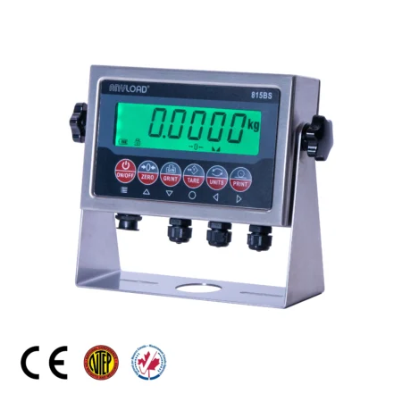
Role and Function of Indicators
Indicators serve as the user interface and control hub of the weighing system. Their primary functions include:
- Displaying real-time weight readings
- General operations like zero, tare, entering ingredient IDs
- Facilitating system calibration and zero/span adjustments
- Allowing configuration of filtering, alarms, tare functions, and batching controls
- Providing input/output control for peripheral devices (e.g., relays, PLCs, valves)
Indicators may be panel-mounted, wall-mounted, or DIN-rail-mounted depending on the application and enclosure requirements. For hazardous environments, explosion-proof or intrinsically safe models may be required.
Signal Conversion and Processing
Modern indicators include high-precision analog-to-digital converters (ADCs) or direct digital inputs (in the case of digital load cells), transforming load cell output into accurate weight values. To maintain stability and performance, indicators typically feature:
- Digital filtering to suppress mechanical vibration, electrical noise, and signal instability
- Temperature compensation algorithms to minimize drift in variable conditions
- Linearity correction, multi-point calibration, and diagnostic functions
These features enable reliable operation even in challenging industrial environments with thermal variation, electrical interference, or process disturbances.
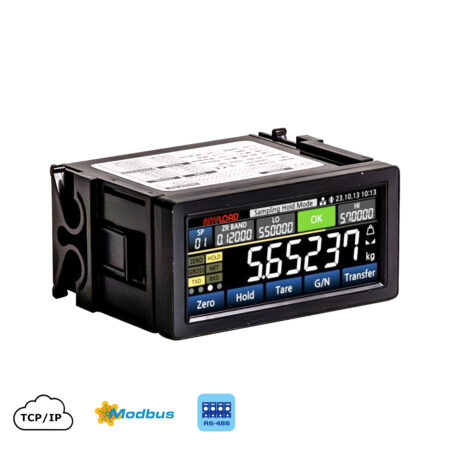
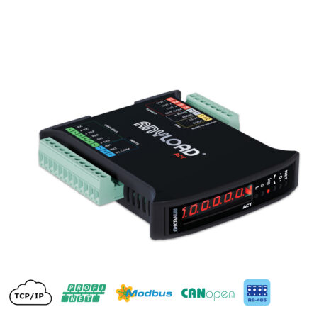
Integration and Communication
Modern indicators and weighing signal transmitters are designed for seamless integration into broader industrial automation and data acquisition systems. They support various industry-standard communication protocols, including:
- Analog outputs (4–20 mA, 0–10 V)
- Serial protocols (RS-232, RS-485, Modbus RTU)
- Digital fieldbus and industrial Ethernet protocols, such as:
- Modbus TCP
- EtherNet/IP
- PROFINET
- DeviceNet, and more
This allows the weighing system to be connected directly to:
- SCADA and HMI systems for centralized control
- PLCs for process automation
- Cloud or on-premise databases for inventory management, diagnostics, and traceability
Advanced indicators may also offer remote configuration and monitoring capabilities, allowing technical staff to diagnose or recalibrate systems remotely without direct access to the scale.
Selection Considerations
When choosing an indicator for a vessel weighing system, consider:
- Number of channels (single vs. multi-channel) for systems with multiple weigh zones
- Required accuracy and resolution
- Environmental rating (NEMA/IP rating for washdown or outdoor use)
- Interface compatibility with existing control systems or networks
- Regulatory certifications, particularly for legal-for-trade or hazardous area installations
결론
A well-executed vessel weighing system requires more than simply placing load cells beneath a tank or hopper. From structural design and weigh module selection to proper installation, integration, and calibration, every step must be carried out with care and technical understanding to ensure accurate, stable, and repeatable performance.
This page has outlined the foundational principles for installing compression and tension weigh modules, the importance of proper grounding, levelling, and alignment, and the role of system calibration and indicator integration in achieving reliable results. Whether used for inventory control, batching, process monitoring, or legal-for-trade applications, vessel weighing systems must be designed and installed to handle the specific mechanical, environmental, and operational demands of their application.
For Product-Specific Installation Info, please refer to the installation manuals of specific weight modules.
The next sections in this guide will explore advanced topics such as thermal expansion, wind loading, seismic considerations, and mechanical compensation techniques. For those looking to specify and build a system, our Product Selection section will walk through how to choose the right load cells, mounts, indicators, and accessories, and how to combine them into a complete, application-ready solution.